Quick Links:
Zen
and Art Home Disclaimer
Errata
Parts and Parts
Vendors
Truck Sales Service
and Repairs
Engine Fuel Hydraulics Radiator and Cooling
Air System Brakes Wheels Tires Electrical
and Batteries
Transmission Clutch Axles Hubs Body Air Conditioning Tools Safety
Hubs
Hubs are my favorite topic. Not. Actually, hubs were the eventual reason for us selling our 1300 and going to the 1017. It was not because the 1017 was a better truck, but the "driving reason" (pun intended) was that it did not have hubs.
I guess I have some strong opinions, but 5 hub failures in 100K miles in 15 years at $1800 in parts per hub can cause that to happen. On one road trip we had 2 hubs fail. On that trip I had a whole set of spare parts with me. But not two sets. Happily, when we went to visit Rob Pickering he had a used set that we installed.
But to be fair, when we had our failure in Helena, MT we installed used gears and bearings but new seals. There were some pits in the bearings and on the bearing races. But that hub made it from Helena, MT to San Diego, CA. Then to Prudhoe Bay, Alaska and back to San Diego (about 20,000 miles) and then to Eastport, ME and finally failed in Denver on our way home. I am guessing that the used components lasted about 30,000 miles total.
I have introspected about my hub failures and have come up with several theories. First, the initial hubs that were changed were damaged before I bought the truck. I suspected that the truck was "submarined" and then left to sit. So, to be fair, 2 of the 5 failures were due to unknown causes. But, the following 3 were during my ownership. I changed the oil regularly and after deep water crossings. But they failed anyway. The reason I believe is that the Unimog was never designed for sustained high speed road travel. In that usage scenario, hubs are a liability. Of course, the exact opposite is true when you are operating off road which is the Unimog's reason for existence. I believe that when I changed the differential ratio to give us a higher top speed on the highway the increased speed combined with high mileage was the straw that broke the camel's back.
There are some that think that the design of the venting of the hubs causes the hub oil to be blown into the axle tube thereby starving the hub of lubrication. This makes sense since high speed travel would cause some foaming in the oil and increases both the temperature and pressure inside the hub. There are aftermarket add-ons that are supposed to address this issue and keep the oil in the hub. Sadly, the hub oil capacity is only about 0.5 liters, so a small loss is a significant percentage of the total. Why the designers decided to do this is a mystery to me.
There are several after-market solutions to the
escaping oil problem. One is shown in the photo
below. I have heard that Von's Mogs also sells a kit for
addressing this problem. Others are available from
Germany.
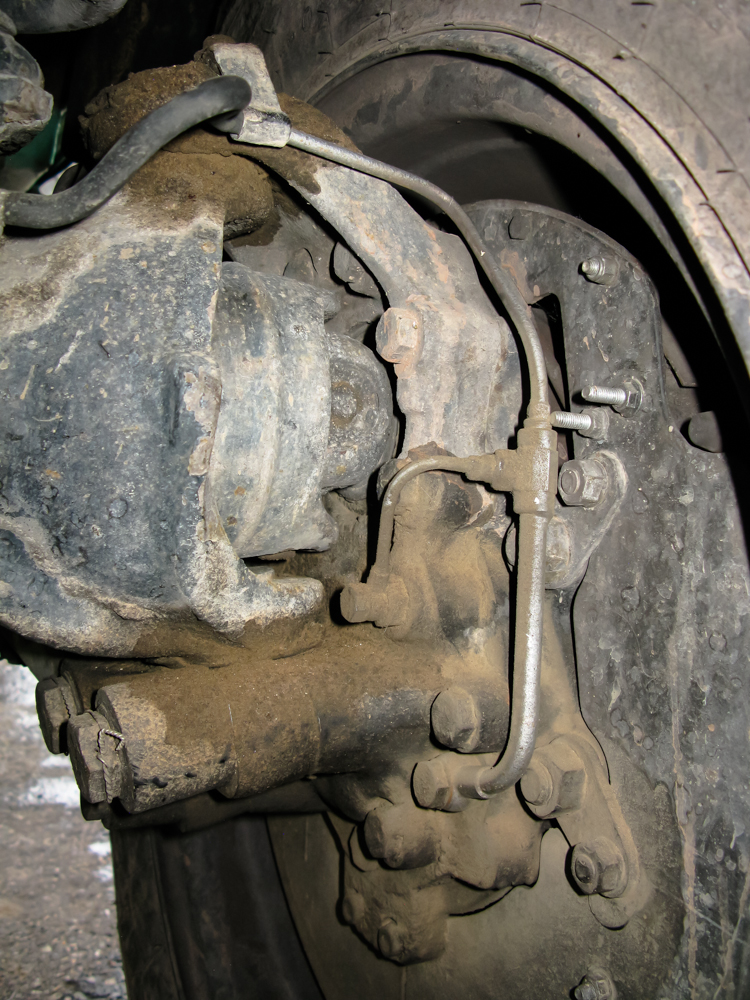
This aftermarket solution to the escaping oil problem is quite
simple. I did not install this on my rig, but rather this
is a photo of a 416 with this installed on the front axle.
This was a home-brew, but seems to have addressed the issue of
the migrating oil.
My truck, with camper, weighed 16,800 lbs which is
a bit over the rated weight. Not enough to cause issues,
but still over. Also, I was running bigger tires than the
stock tires. Each of these issues may have contributed to
the failures. I doubt that we will ever determine a
definitive cause. Benzworld.org has a thread on this very
issue and the conclusion that was reached by some extensive
testing by one of the forum members was that the oil migrates at
high speeds and never comes back.
So with these failures, I am somewhat of a
reluctant expert on hubs, although not by choice. The
sections below will outline the service process and discuss some
things that can be done to stave off hub failures. I
strongly suggest the purchase of the Unimog shop manual if you
are going to be performing hub service.
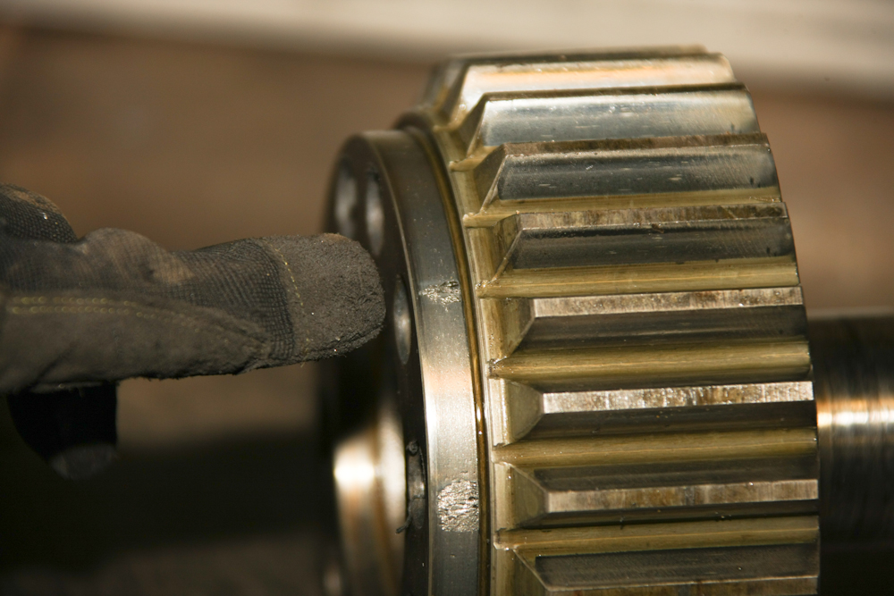
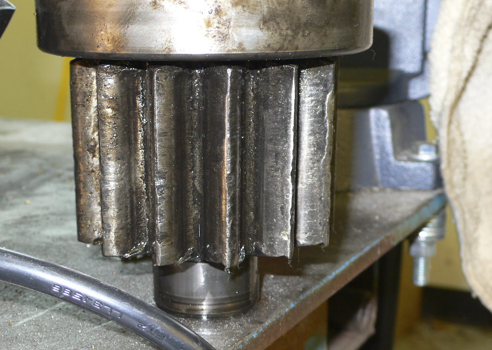
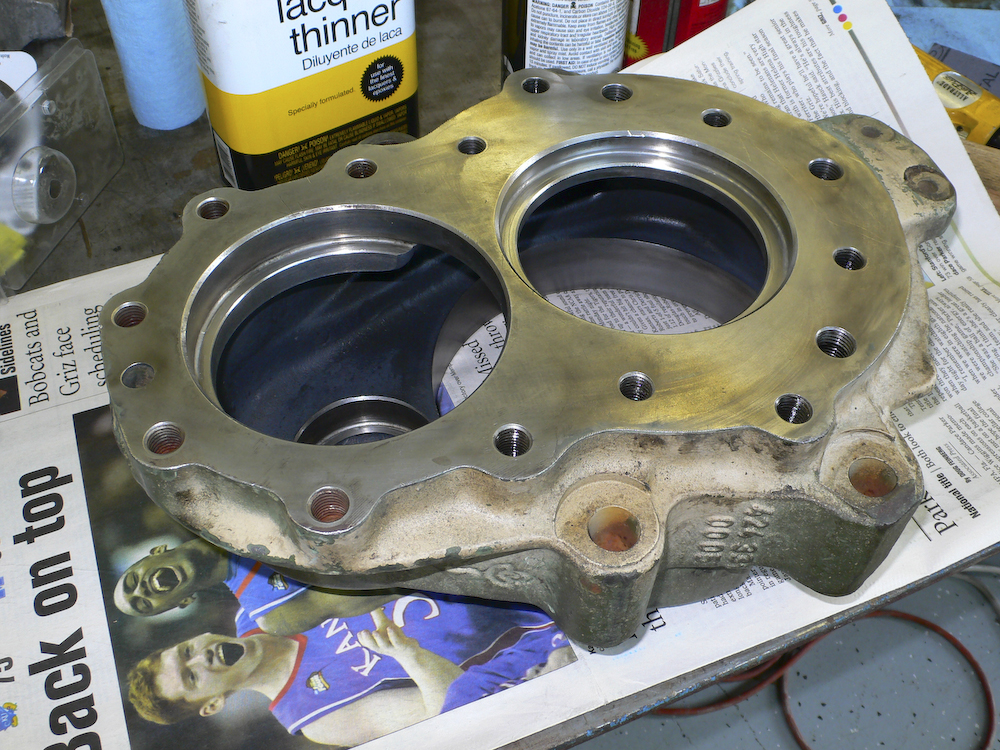
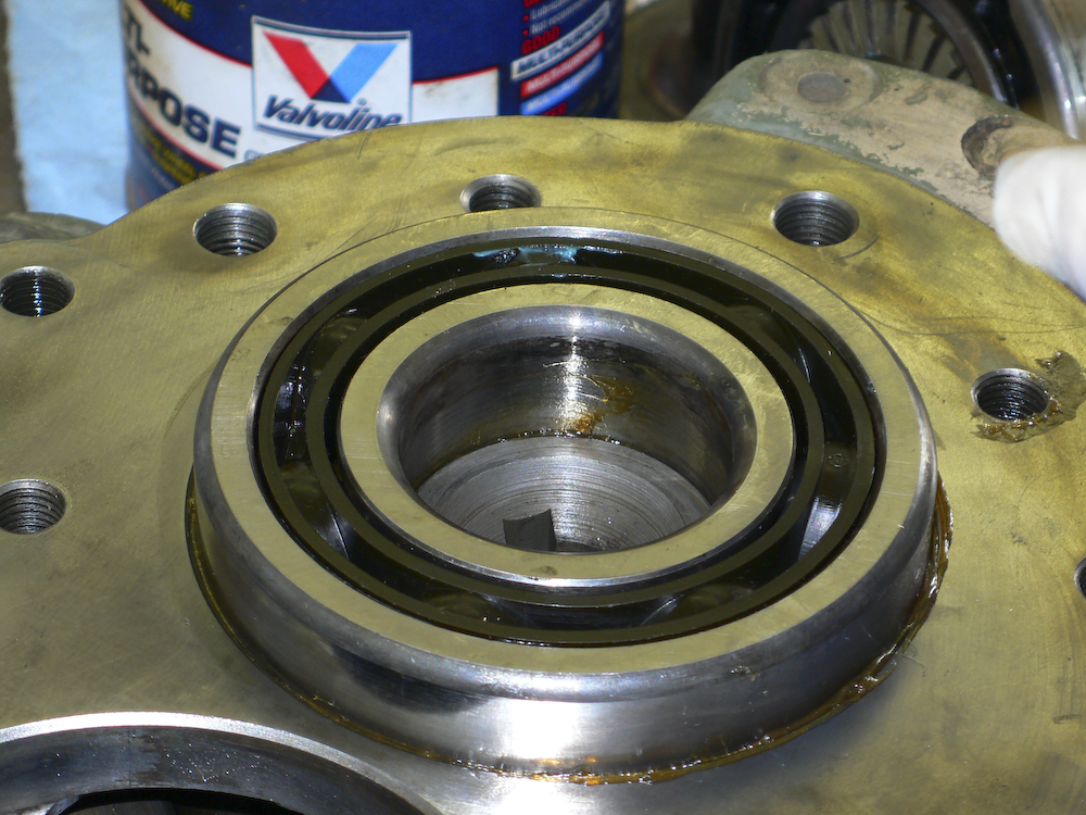
Another thing about the design of the Unimog hub
as that a surface on "driven" gear serves as the inner bearing
race for the constellation of roller bearings on the outside of
the hub. While this spreads the load over a large surface,
it also means that when there is wear, the whole gear has to be
replaced, even if the gear teeth surfaces are good. These
gears are big and heavy and therefore expensive. The photo
above shows one of the gears that we pulled out and the trough
that was worn in the surface by the roller bearings is
visible. Also visible is the surface degeneration that is
likely due to wear penetrating the hardened surface of the
bearing area and down into the base metal.
Check your fluid levels regularly
Since the fluid capacity of the hub is so small, it really is a requirement to check the hub oil levels frequently. And surely check it before any major trip. See photo below for drain, fill and check port locations.
Specific fluids to use is a sensitive topic with
some folks. 80W gear oil works fine. That said, we
did a test using hub temperatures as the guide and found out
that Amsoil "Severe Gear" oil provided hub temperatures that
were a full 10 degrees lower than those produced with regular
80W. I think that a multi-viscosity oil is a superior
choice, but much more expensive. Also, I think that
synthetic oil is probably better that the organic oil.
But, whichever oil you choose, insuring that the hubs have
sufficient oil is more important than the specific oil.
Running a hub on any oil when the level is low will produce an
expensive, time consuming failure.
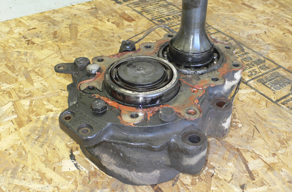
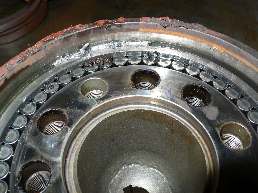
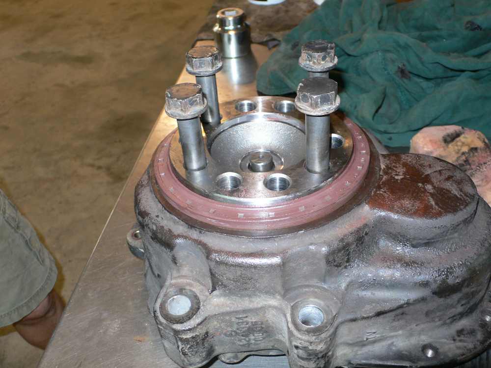
I could not find a photo of the hub mounted on the truck that
should the oil access ports clearly, so this is as good as I can
do. The access ports are the 3 bolt heads visible on the
red surface. The left most one, which is the bottom of the
hub, is the drain. The others are the fill and level
check. Each of these has a copper washer that is needed to
keep the ports from seeping and/or letting contaminants into the
hub. When you change the hub oil, insure that your drain
bolt has a magnet in it. If it does not, you can order one
from your favorite parts vendor. The magnet will pick up
any small debris from the oil and will allow you to assess a hub
that is dying before it actually does a face plant. The
hub assembly in the photo above is toast. Note the gray
goop on the shaft sticking out - those are metal particles from
failed bearings.
An easy way to check the hub, is to remove one of the 2 upper
plugs and just stick your finger in the oil (when cool, of
course). If the oil comes back looking like metal flake
paint, you have a failing hub. If you jack up the
suspect corner of the truck and spin the tire (with parking
brake released for the rear and the wheels chocked) you may
hear a grinding or rumbling noise. This means you have a
failing hub. If you see oil (not brake fluid) leaking
from the seals, you need to immediately check the fluid level
in the hub. I STRONGLY suggest that you carry at least
one full quart of gear lube with you in your rig. And,
for normal gear oils, you will need a hand operated pump that
goes into the bottle to get the oil into the
conveniently-located hub access ports.
One item that we found to be very useful is an infrared thermometer. IR thermometers can be obtained at Home Depot or any auto parts store and they will allow you to check the temperature of the hubs when you stop for fuel or a bio-break. You should note both the ambient temp and the temp of each of the hubs and record the values in your log book. Many times, when one of the hubs is running hotter, it means that it MAY be on it's way out. I say "may" because several of our failures were not accompanied with elevated temperatures.
The hub repair kit consists of a driver gear, a driven gear,
4 bearings and 2 oil seals; see photo below. You may have to
replace the "wear ring" that the seal rides on as well if it
is grooved and you cannot position the seal to avoid the
grooves. But, as a side note, you can sometimes adjust
the location of the seal on the ring to gain extended service
life. But before you decide to do anything fancy,
remember that you have about $2K of parts at risk should the
seal not do its job because you short-sheeted the parts being
replaced. Be aware that with the exception of the inner
oil seal, all the parts are common to each hub. Stated
differently, if you have to carry a spare parts set, get both
front axle inner seal and rear axle as well as the gears,
bearings, wear ring and outer oil seal. Then you can
handle a failure on either front or rear axles.
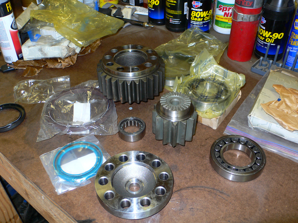
Hub replacement parts. Clockwise from
the top: driven gear, outer lower roller bearing
constellation, inner lower bearing, driven gear, upper inner
bearing, wear ring, inner oil seal, lower oil seal and upper
outer roller bearing.
A badly failed hub is never a pretty sight. Or smell. The sulfur in the gear lube smells like the devil's own ass. In the photo above, the driver gear has suffered melted faces on the teeth. We had to drive this hub for over 50 miles over MacDonald pass outside of Helena, MT to get to a place to do the repair.
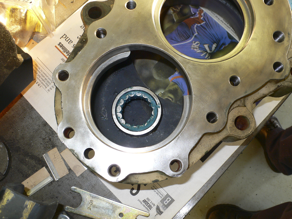
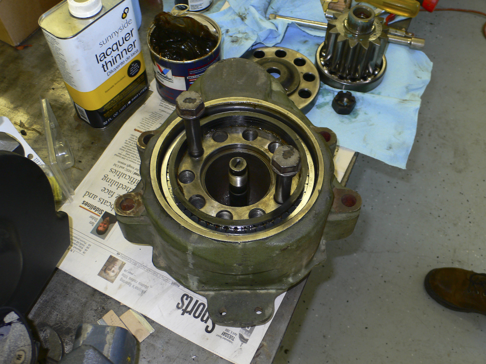
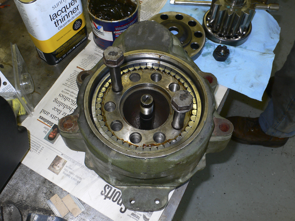
We got this hub into the shop before the whole
assembly melted down. This hub shows the typical failure
mode which is the rollers eating into the driven gear.
Note the metal particles.
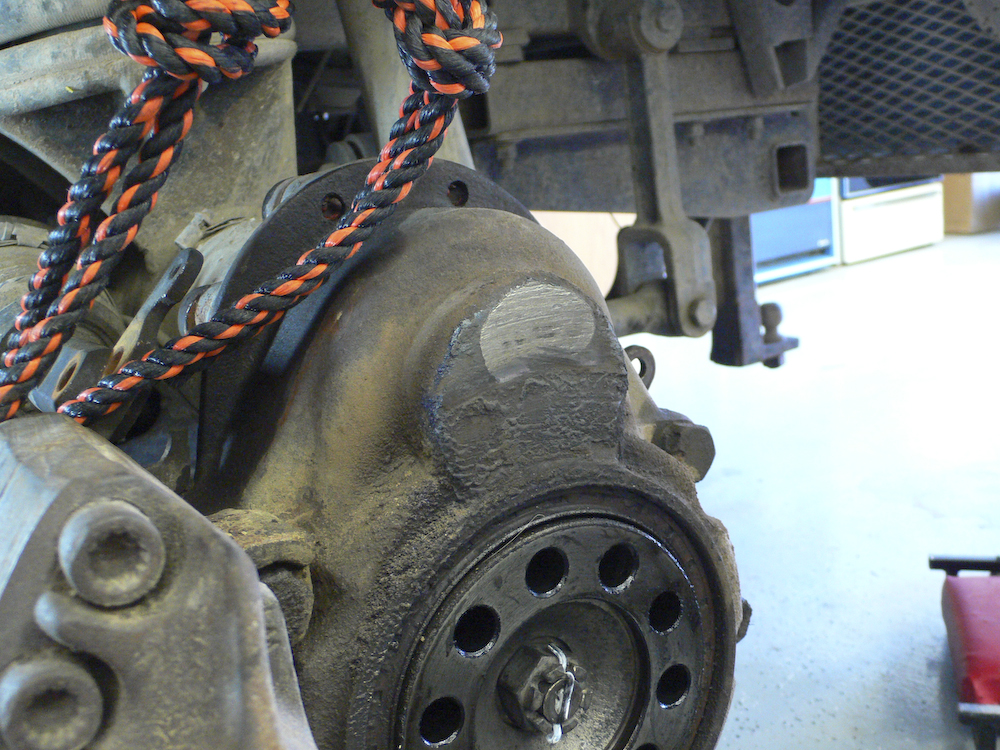
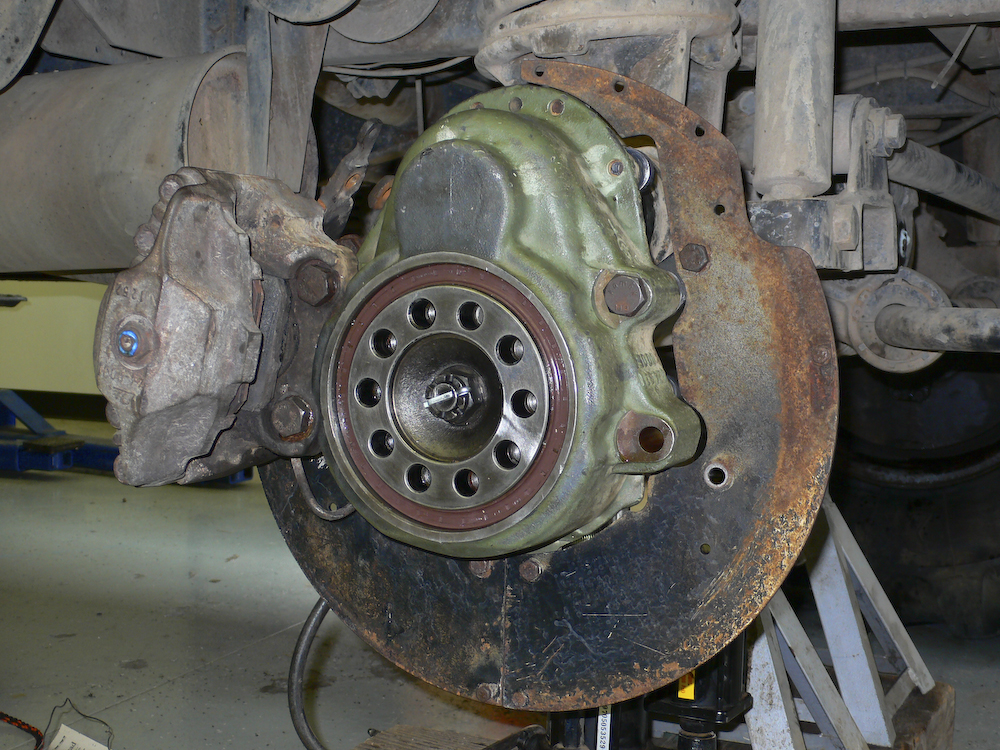
One hub failure resulted in the bearings being
eroded so much that the brake rotor was allowed to come in
contact with the hub housing, damaging both the rotor and the
housing. Note the ground off portion of the hub.
This casting was toast; the large bearing spun in the casting
damaging it beyond further use. The rotor was damaged as
well, but it lasted until the next replacement cycle.
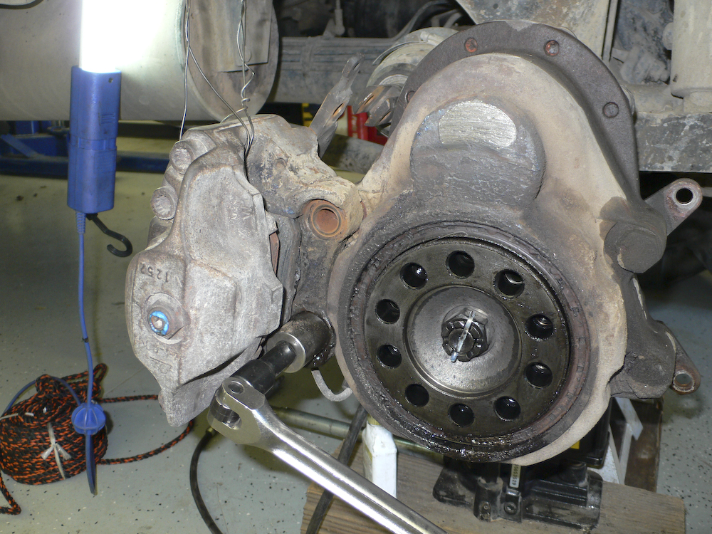
If you do not plan to detach the brake calipers from the
brake system, you can hang them from the truck body with
baling wire. Also, the bolts that hold the caliper to
the hub are tight, so a robust, hardened socket and breaker
bar with cheater will be required. In this photo, the
bottom bolt was the zero-clearance body bolt. Insure
you note which hole it came from so it can be reassembled
the same way. Also, during reassembly, be sure to use
anti-seize on the bolts and nuts. You will thank
yourself later. Build air pressure and engage the
differential lock. Remove the cotter pin and loosen
the castle nut while the assembly is still on the
axle. The first time we did not do this and it makes
things harder.
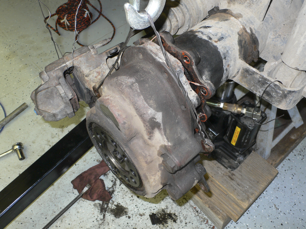
The hub assembly is heavy and you should consider using an
engine hoist to lift it during the service process. It
saves the back and prevents it from being dropped on your
foot possibly damaging your foot or the hub casing. One of
those two is replaceable, the other is not. To
separate it from the hub mount required some rubber mallet
work to crack it loose.
We cleaned and inspected the old hub casting and found it damaged beyond further use. A used casting was obtained from Rob Pickering at Terry Lee Enterprises and was cleaned and ready for installation.
The smaller roller bearing installed in the housing.
This is also called the upper outer bearing. It gets
tapped in with a plastic mallet and soft metal punch or
bar. Easy and slow will win this battle; you do not
want the bearing cocked in the cup as it is hard to get out.
Next, the driven gear is placed in the housing gears down (out) and the lower inner bearing is tapped onto the gear shaft and into the housing.
The bearing is seated but the gear will need to be driven
back into the bearing. You will have to brace the
bearing to prevent it from being pounded out.
Civilized mechanics use a hydraulic press and we would have
as well if we had access to one. Instead we used a
dead-blow mallet and some time. Slow, but it did
work. You can also use the castle bolt and wear ring
to help seat these parts together.
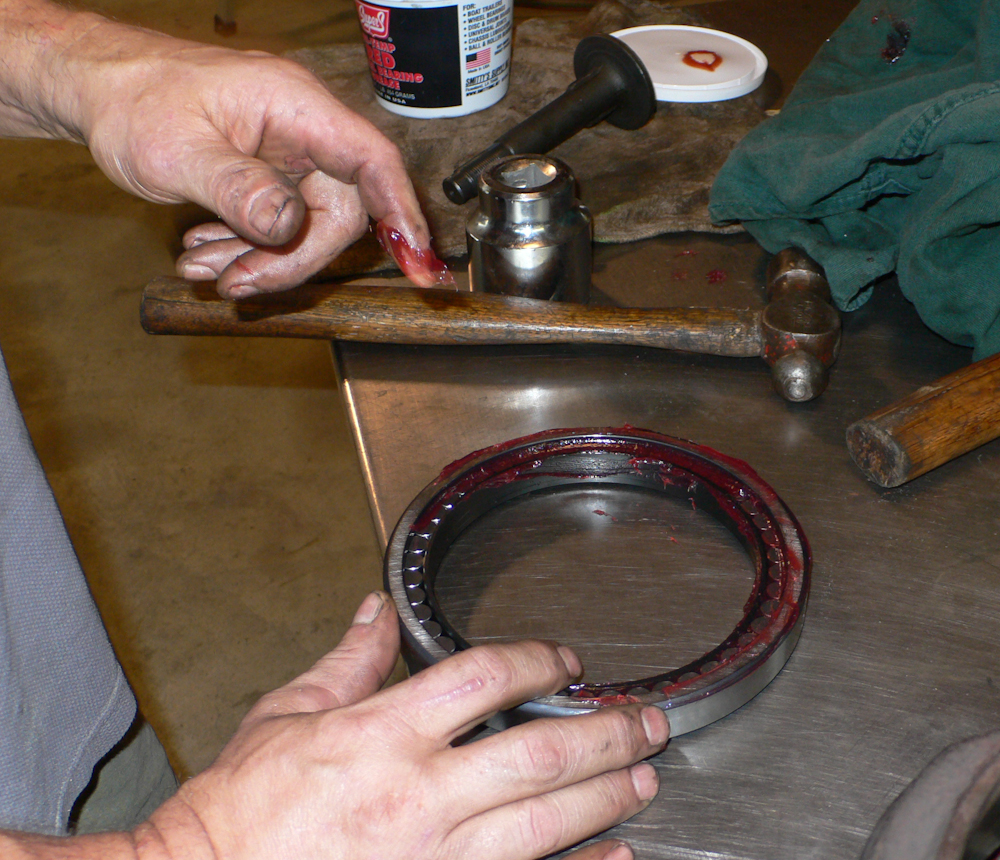
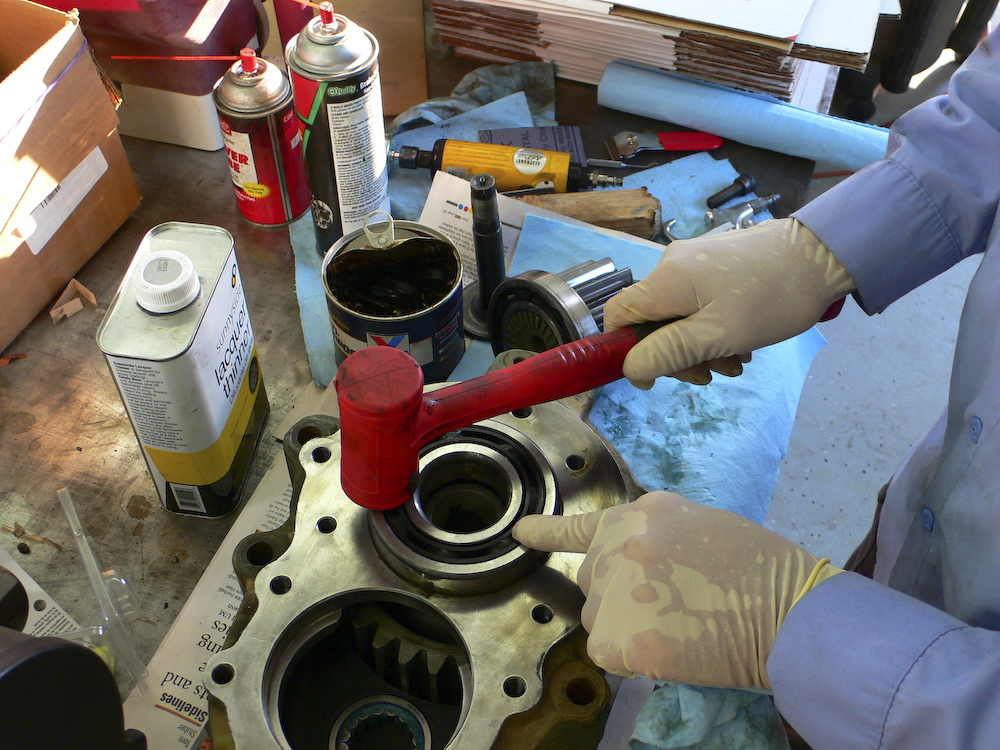
This is the "lower outer" roller bearing that always seems
to fail first. This is a big bearing, but it does not
have an inside race. Sadly, Mercedes elected to use
the surface on the driven gear as the inner race thus
assuring that when there is wear you have to replace the
whole gear rather than just a bearing. Look carefully
at the photo above and you will note that there is a plastic
retaining ring on the inside. This ring holds the
rollers in place until it is time to slip over the wheel
gear (driven gear). Inspect the next photo carefully
and you will note the ring being displaced as the bearing is
being seated. Note the castle bolt next to the bearing
grease at the top of the photo.
To seat the outer lower bearing we used a small punch and then tap-tap-tapped our way around the circumference of the bearing repeatedly to get it to seat. We coated both the outside of the bearing and the inside of the housing with a light coat of axle grease to prevent binding. Note that the retaining ring for the rollers is being displaced as the bearing is being seated. This prevents the rollers from scattering to the four winds during the process. The hub bolts were screwed in to allow moving the gear if required. There several things going on at once during this process. You are seating the bearing, but you are also seating the gear into the lower inner bearing at the same time.
The same process a bit further along. Note that the retaining ring has popped out while the constellation of rollers are in place. Also note the retaining bolt that goes through the center of the driven gear. SUGGESTION: it is easiest to loosen the castle nut on this while the hub is still attached to the axle. With full air pressure, engage differential lock and get your hardened socket with breaker bar and crack it loose. Likewise, tighten it to full specified torque after it is back on the truck. See shop manual for specified torque (it will be tight). BUT YOU HAVE TO REMEMBER TO TIGHTEN IT. This bolt holds the driven gear in the hub casting and if it is loose nothing good will come of it. And remember to install the cotter pin after the castle nut is tight. Also note in the photo above just above the hub casting is the wear ring. The wear ring provides the seal between the spinning gear and the lower outer oil seal. The ring is shown with the hump up on the table. When assembled, the hump fits into the grooved area in the driven gear.
Installing the wear ring and the oil seal requires keeping
the wear ring in place while the seal is tapped in with a
punch and mallet. Slow and easy wins this
battle. Put a light coat of grease around the
circumference of the wear ring and on the inside of the
seal.
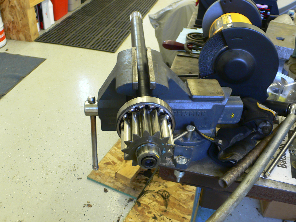
THIS IS THE WRONG WAY TO DO THIS!! We had not deduced the "use the axle and diff lock" technique yet. The vice could not hold the axle shaft sufficiently tight to provide full torque.
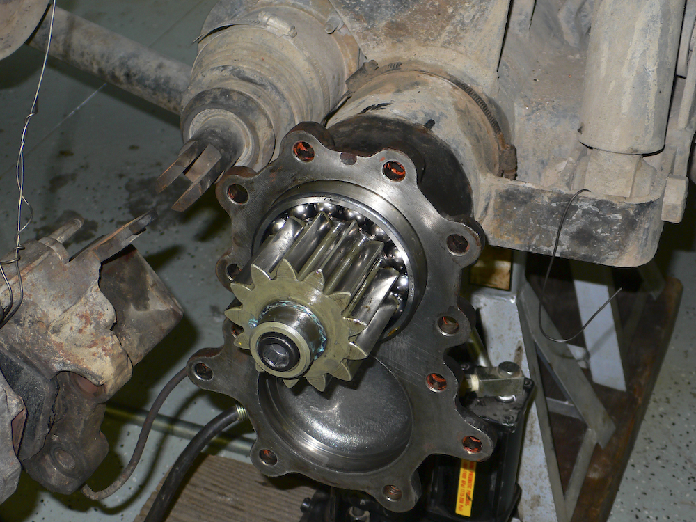
This is the better way. Hand tighten the gear to the axle with your allen wrench. The bearing should already be on the gear. Stick the assembly in the axle, engage diff lock and tighten the bolt to the full torque specification. Note the pocket in the hub mount below; the associated gear is held into the hub casting via the castle nut described above and will be seated when the assembly is bolted to the mount.
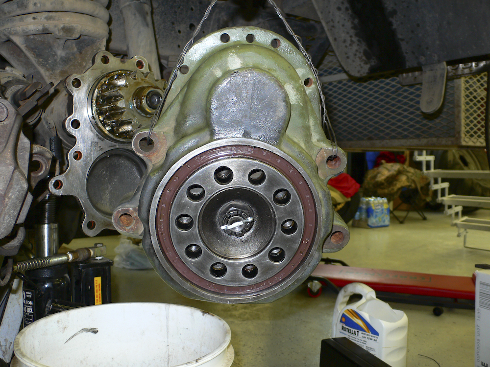
The finished hub assembly is being lifted back onto the hub
mount. Note that the wear ring and outer lower oil
seal have been installed. Also, the castle nut has
been installed and tightened. I recall that in this
case, I tightened the nut by installing several hub bolts
and using them as a fulcrum for the tightening
process. Using the diff lock is safer, easier and will
allow you to easily check the torque. WHEN YOU GET READY TO
REASSEMBLE THE UNIT, DON'T FORGET THE GASKET SEALER.
IT WILL LEAK UNLESS YOU USE SEALER. Apply the sealant
around the entire face of the casting
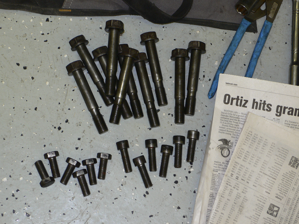
Time for the final assembly. Note that the hub bolts are special. Not only are they hardened, but they have a neck-down as well. Insure that these are clean, free of debris and that the threads are not damaged.
Next install the caliper(s). Remember to put the body bolt into the same location and to use anti-seize on both bolts and nuts. Then install the stone shield at the back.
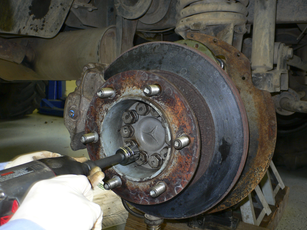
Next comes the brake rotor and the hub. Getting these aligned is hard, we used a hydraulic jack as an adjustable support for the heavy rotor to make life easy. You can see the jack at the bottom of the photo. Once you can get 2 bolts on opposite sides in, the balance is easy. The hub will have to be tapped into position as it is an interference fit inside the rotor. INSURE THAT THE HUB BOLTS ARE TO THEIR FULL SPECIFIED TORQUE. These bolts hold the wheel to the axle and if they are loose bad things will happen next. I also suggest that you use anti-seize on these bolts. They are difficult to get out if they are rusted; you will break sockets and/or breaker bars trying (ask me how I know).
If you are really good and you have your act together, all the correct tools and parts and luck is with you, you may be able to complete a hub service in about 10 hours. These conditions are rarely, if ever, likely to occur so 2 full days would be a good execution time although it will likely be longer. If you do this outside, be sure to cover your work with a trash bag and tape or a tarp and bungees to prevent rain or dew from contaminating the components.
Doing a hub is a real hassle. We have
been fortunate that the failures we have had were
sufficiently close to a shop that we did not have to do this
on the side of the road. There is some good in every
bad situation I suppose.
Quick Links:
Zen
and Art Home Disclaimer
Errata Parts and Parts
Vendors
Truck Sales Service
and Repairs
Engine Fuel Hydraulics Radiator and Cooling
Air System Brakes Wheels Tires Electrical
and Batteries