A lot
of planning and test fitting was required before final mounting
locations were chosen for the inverter and solar support
equipment. Cable routing needed careful consideration as
many of the routes were difficult to access or required removing
appliances to gain access to the cable route.
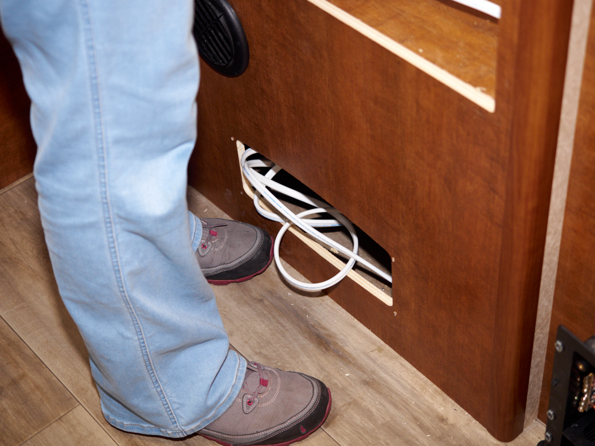
The photos below are what we saw.
We
needed to access both the refrigerator compartment and the
heater compartment directly below to route our cables. We
used Ancor marine safety cable for both AC and DC wiring.
This wire is expensive, but the best available.
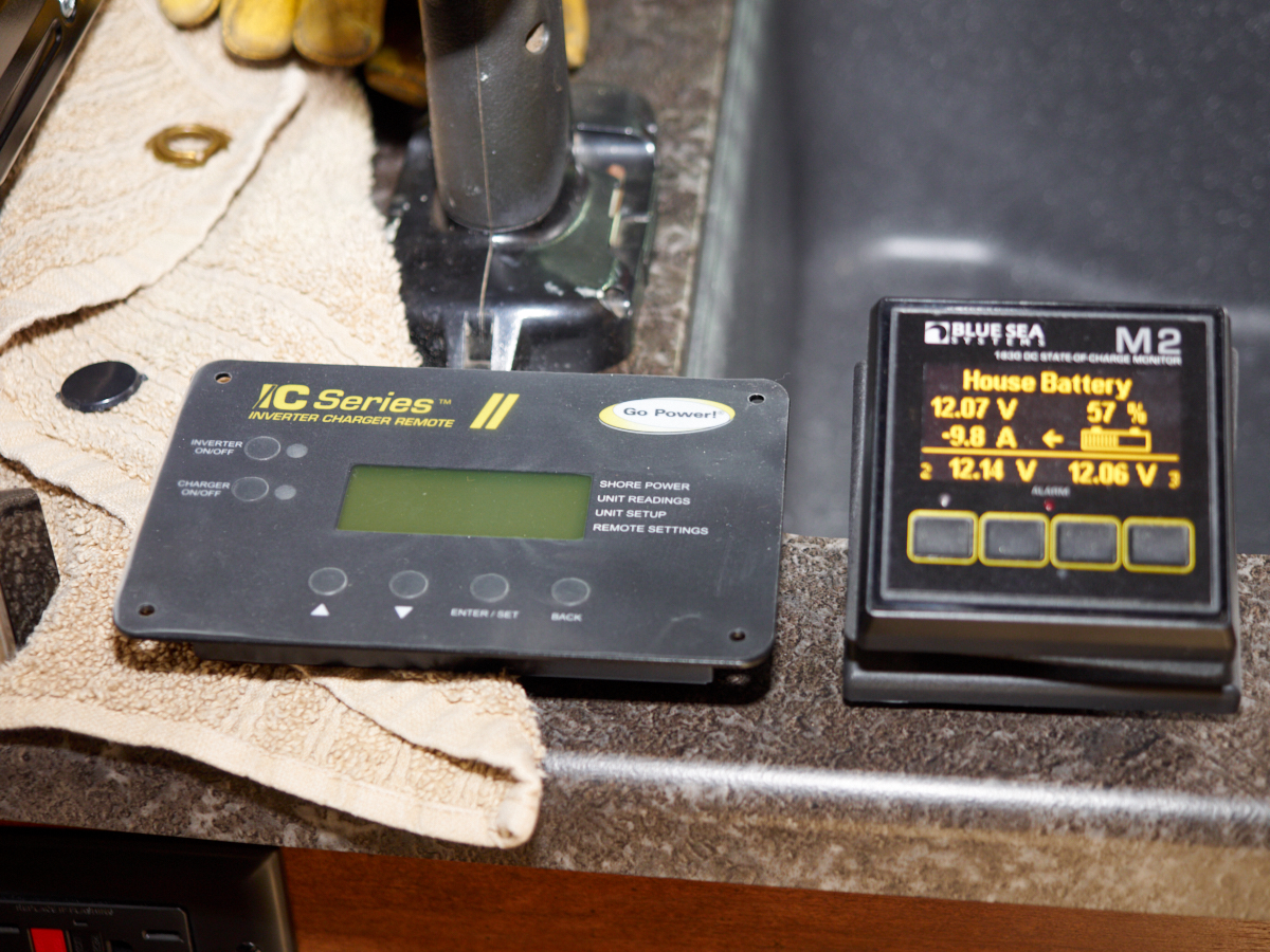
We
needed to mount two meters on the wall. To the left is the
remote control terminal for the inverter. On the right is
a Blue Sea Systems "State of Charge" digital panel meter.
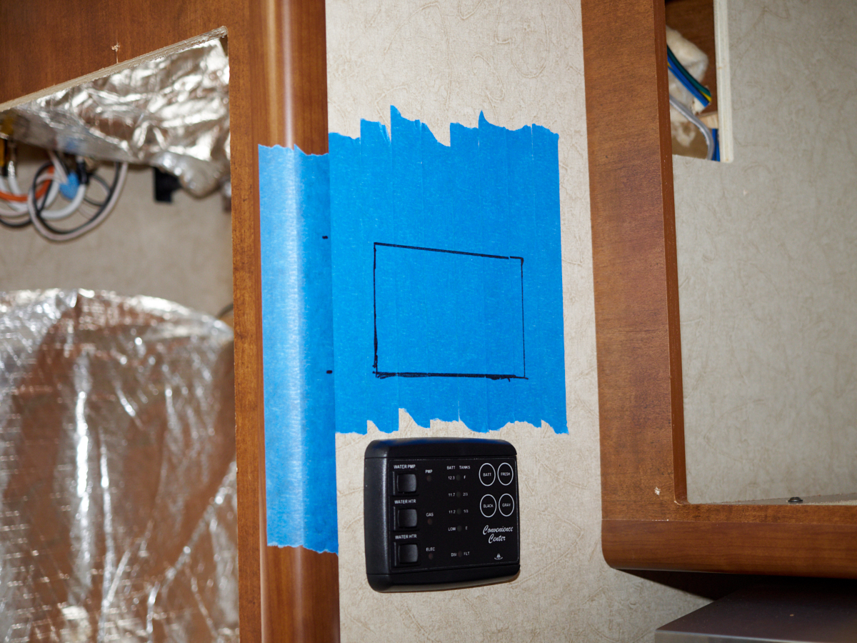
The
inverter remote control was the bigger of the two and was
installed first. 3M blue tape was applied to provide some
protection from tool marks.
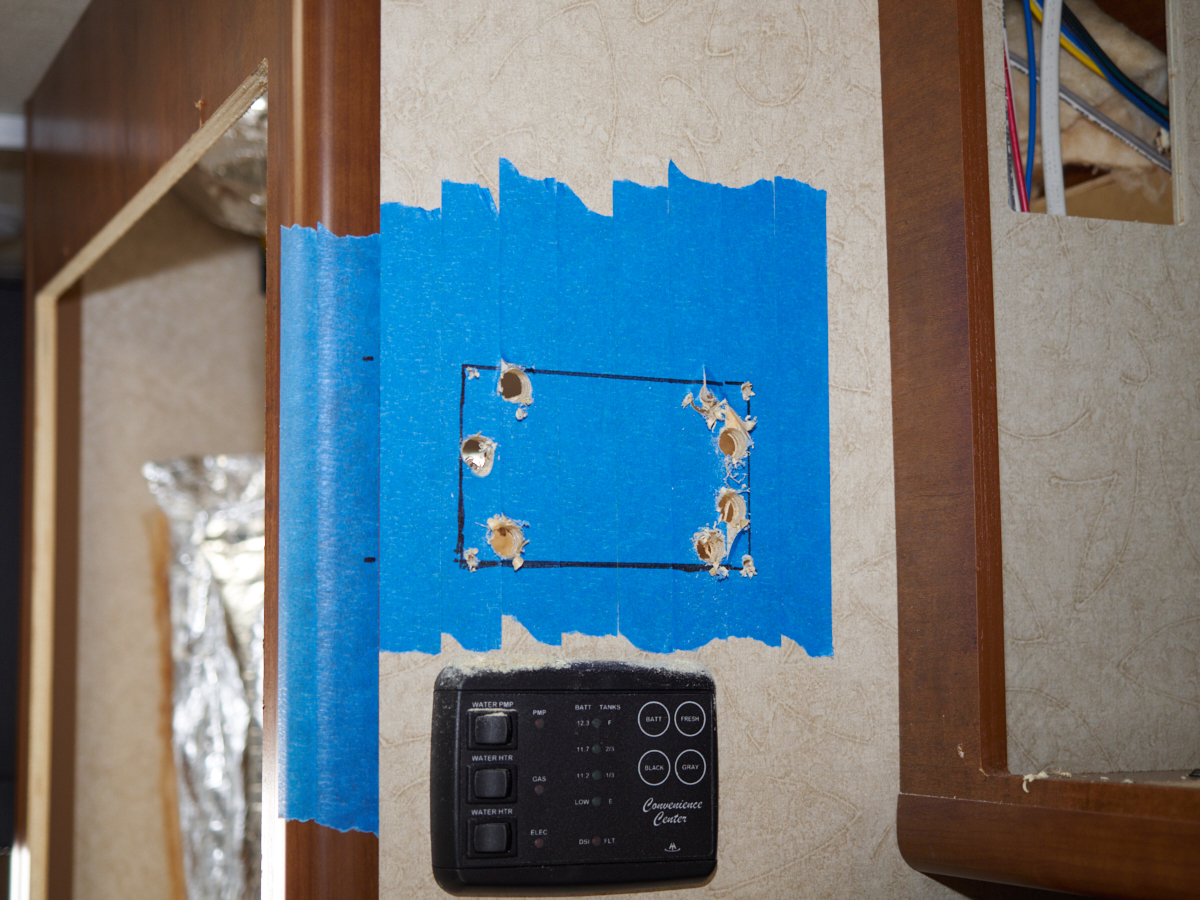
Holes
that were big enough to pass the saw blade were drilled in the
10mm plywood walls. The jig saw was inserted and cuts were
made to remove the balance of the material.
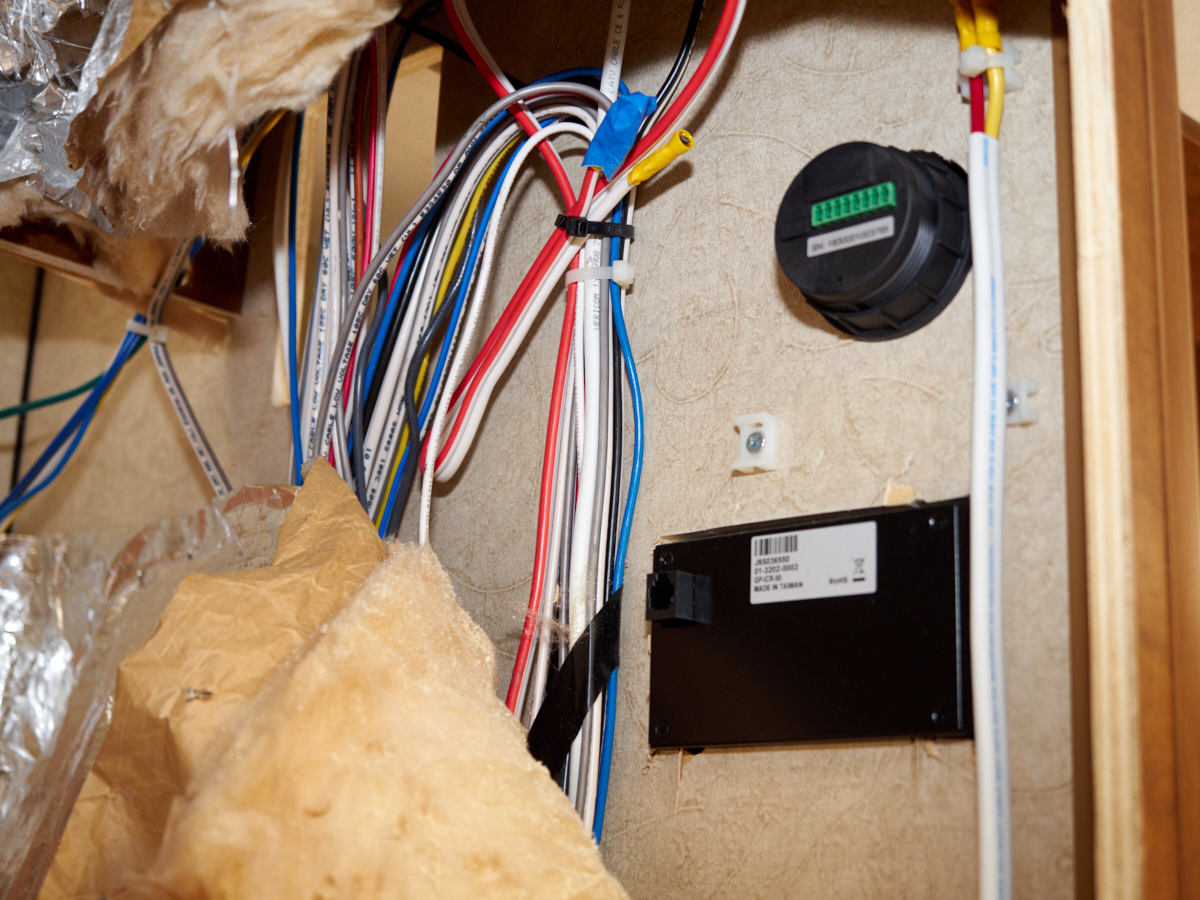
The
State of Charge meter was installed with a simple 2" hole
saw. Note the size of the existing wire bundles.
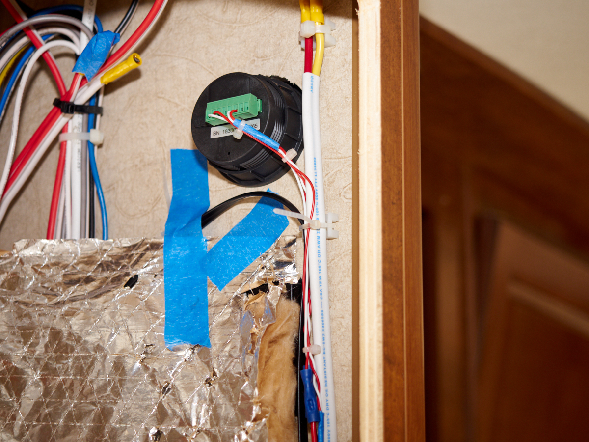
A
twisted pair harness was prepared and combined with some power
feed lines to supply the small meter.
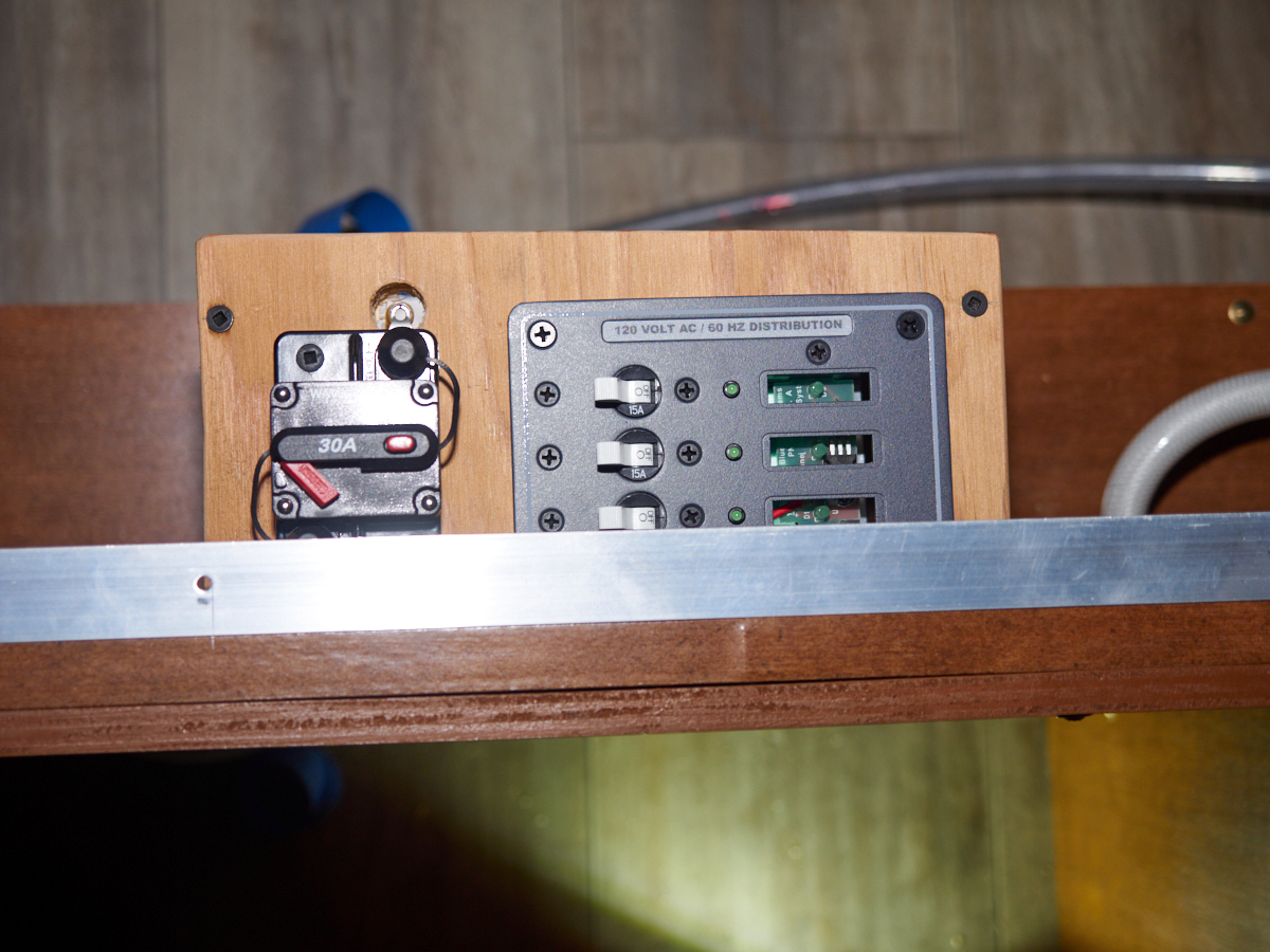
The AC
subpanel and solar circuit breaker were attached to the wall.
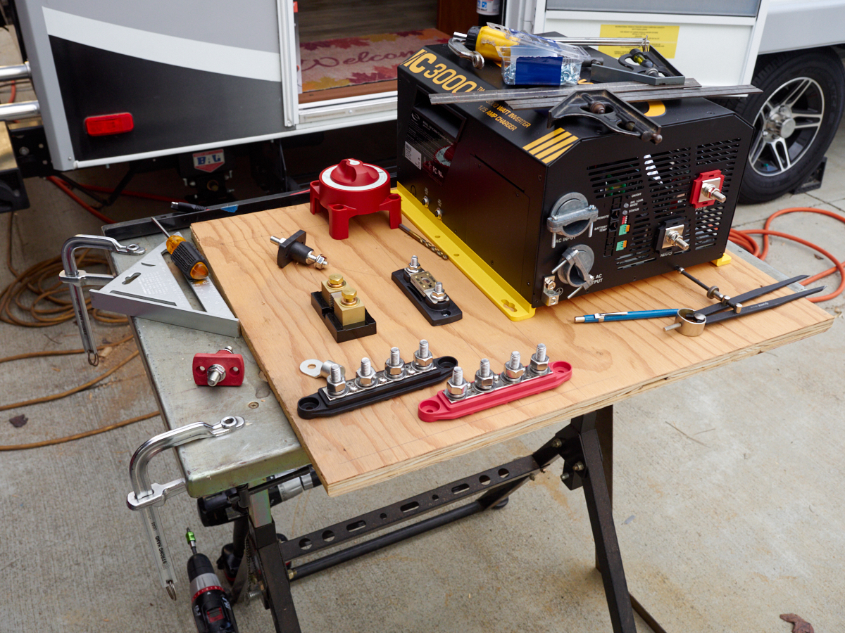
The
below-the-bed cubby was measured and a plywood mount for the
inverter and high-current DC lines was prepared. The
components were arranged on the mounting board to test the
layout.
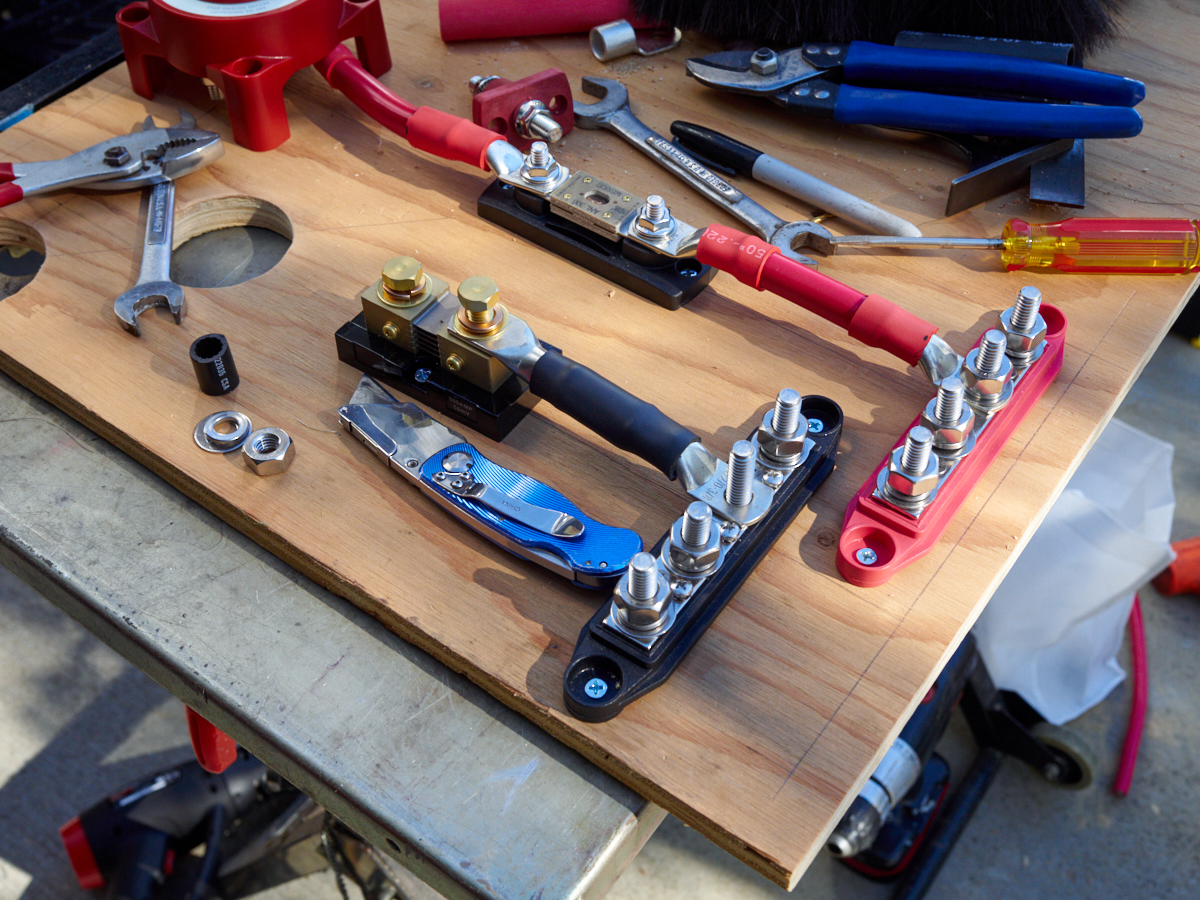
Components
were attached to the mounting board and connecting cables were
cut and fabricated.
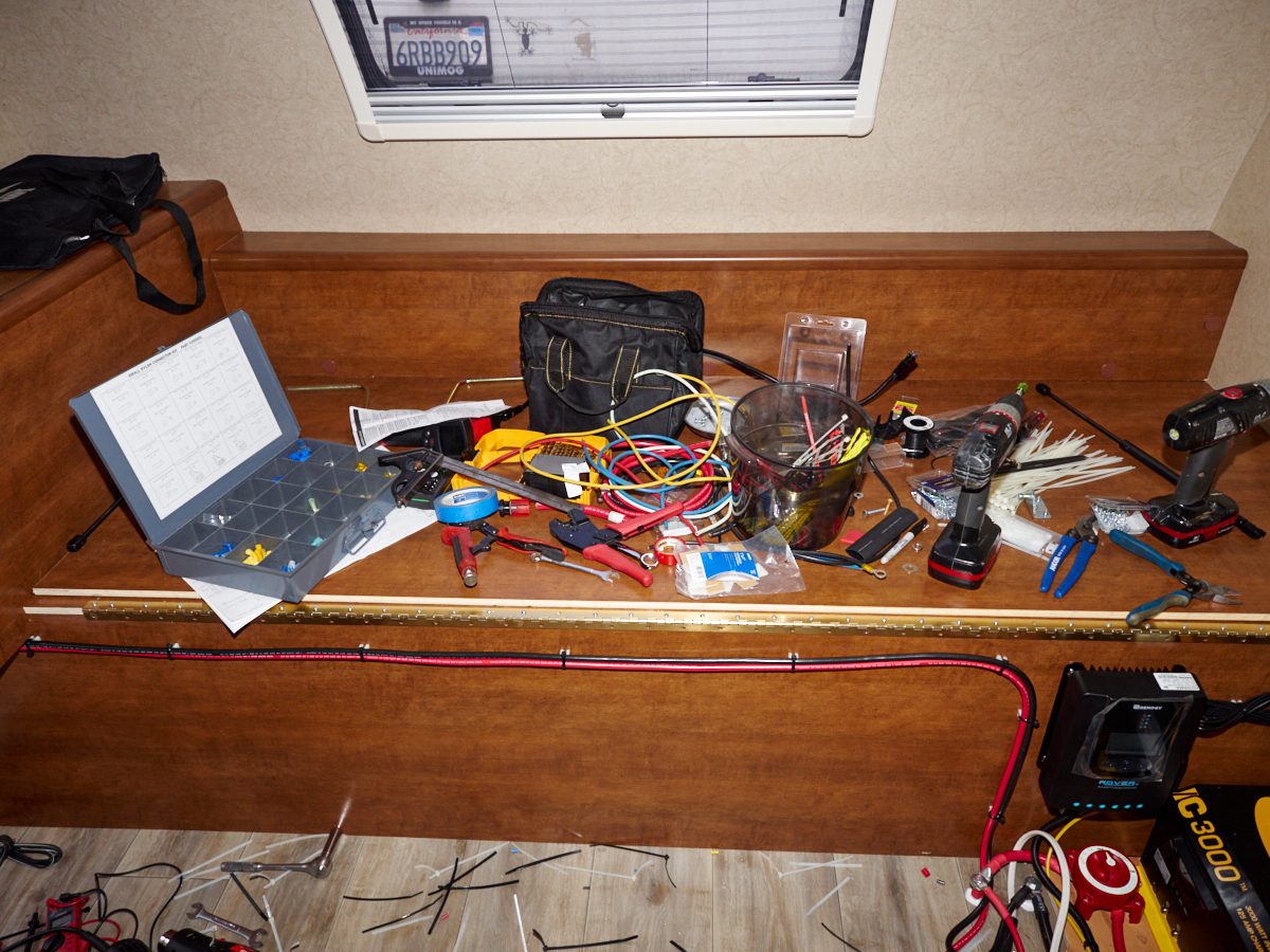
Meanwhile,
the inside of the camper was turning into a cesspool of tools
and zip-tie clippings.
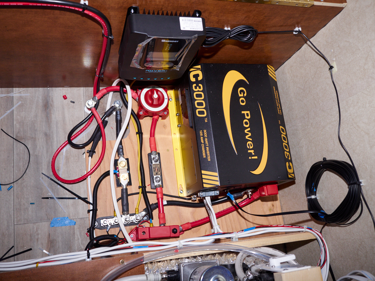
The
solar charge controller was mounted on the forward wall of the cargo
compartment and the cables were dressed and attached using
screw-type zip-tie mounts. The #4 AWG cables were
repositioned for circuit testing. During normal operation,
they will be attached to the DC buss bars at the bottom of the
photo above.
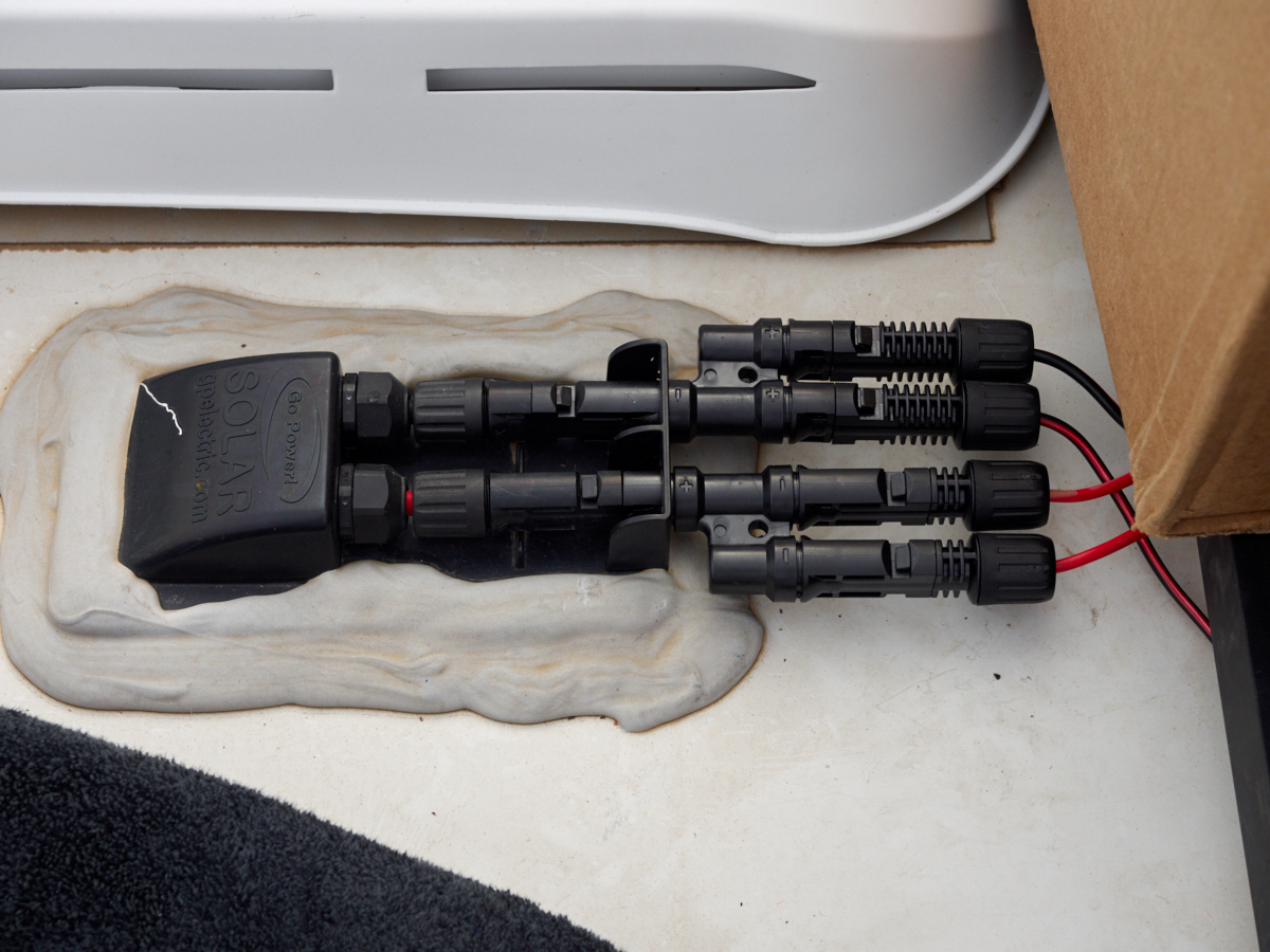
Once the
installation and preliminary wiring was completed, we attacked
the solar installation. Panels were recovered from their
installation on the HiLo and moved to the Lance. The Lance
came from the factory pre-wired for solar including a
through-roof mounting setup. I had to acquire MC4 cable
connectors (Amazon) and then attached these connectors to the
wires from the panels. I also purchased Y connectors that
allow parallel connections of multiple panels.
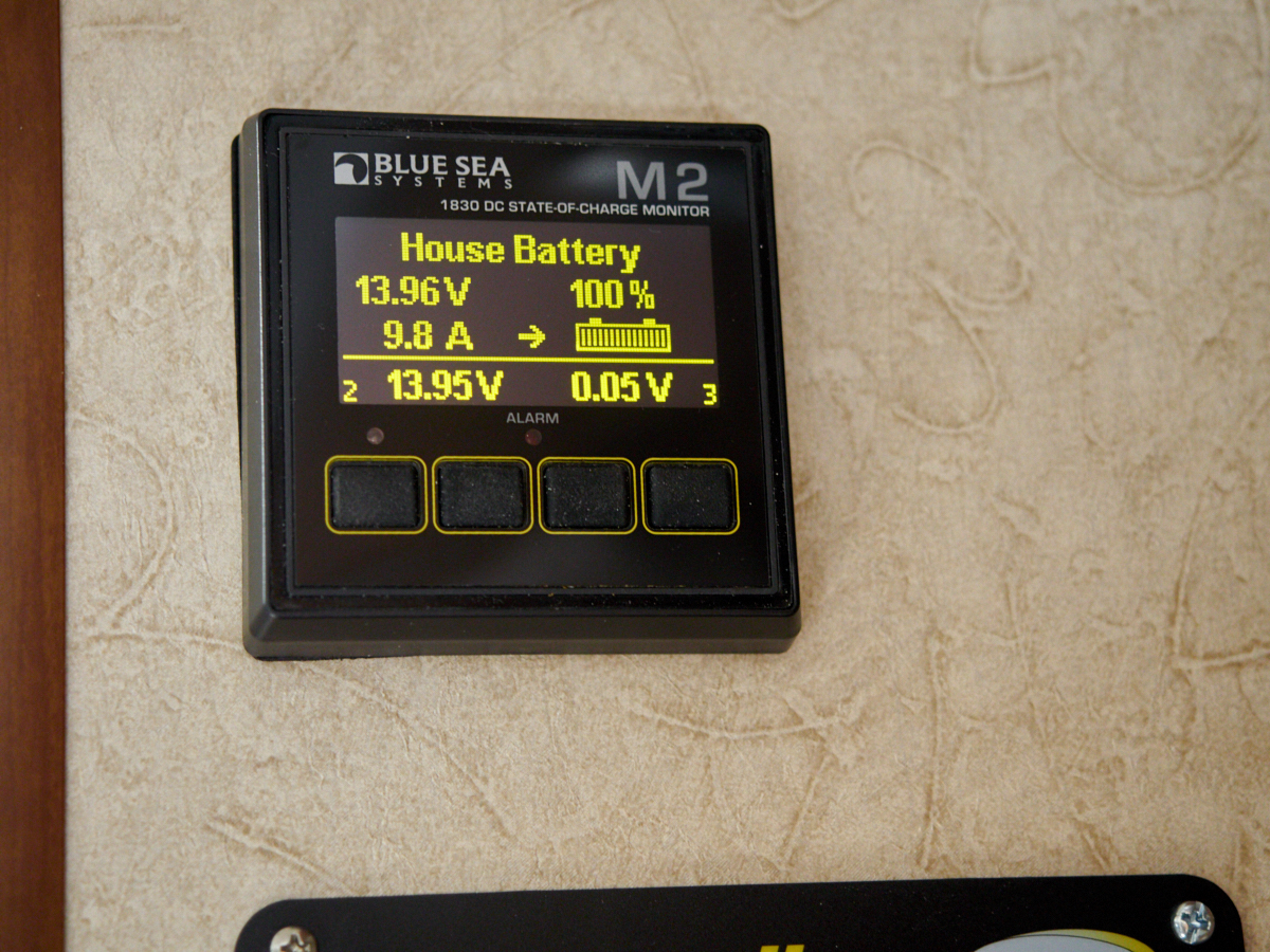
Once the
panels were installed and the circuit turned-on we were able to
verify the operation of the SOC meter and the polarity of the
current-sensing shunt.
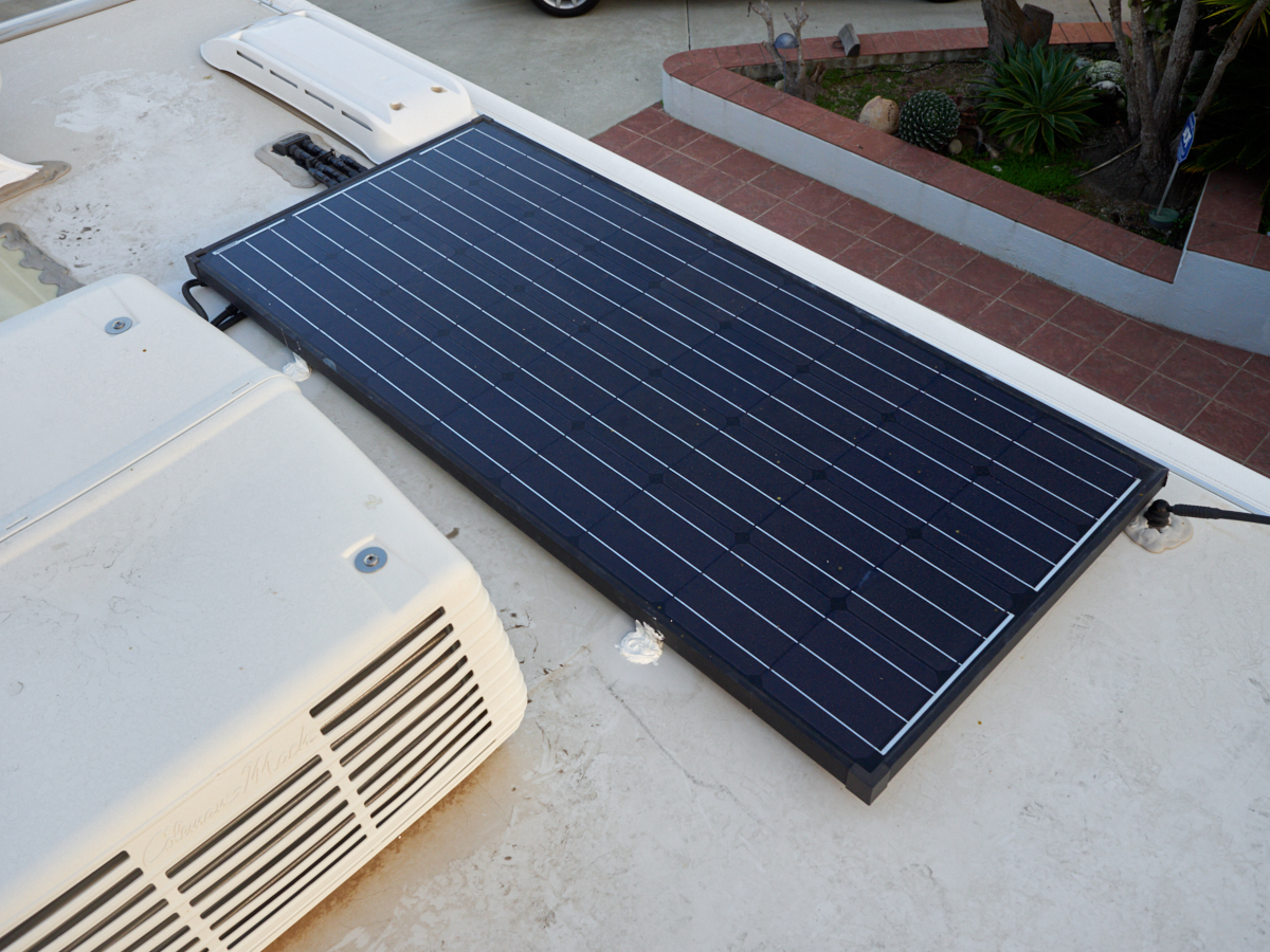
My buddy
Vince came through town and he helped us affix the panels to the
roof of Lance. We used 1/4" pop rivets and 3M 5200 marine
adhesive for the installation. Note the white blobs on the
roof. We applied a generous coating of the 5200 adhesive
to insure that there were no leaks in the cover membrane.
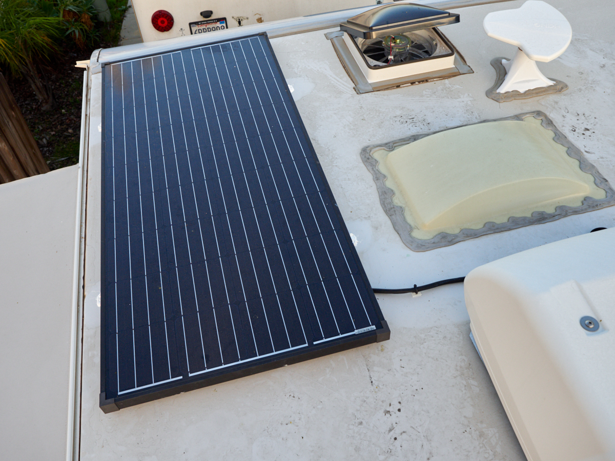
Visible
in the photo above is the second solar panel, Fantastic fan and
digital TV antenna.
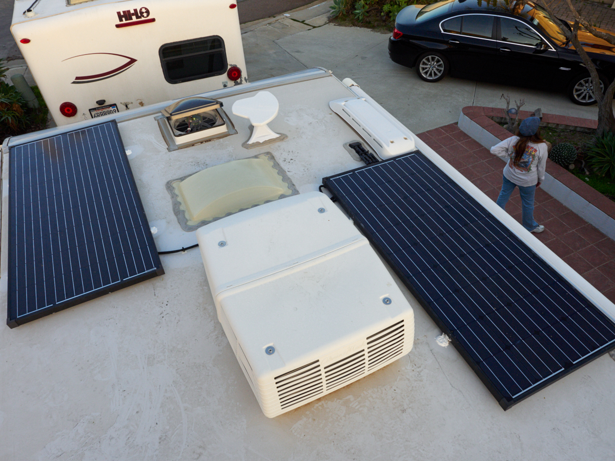
We were
pleased with the final installation.
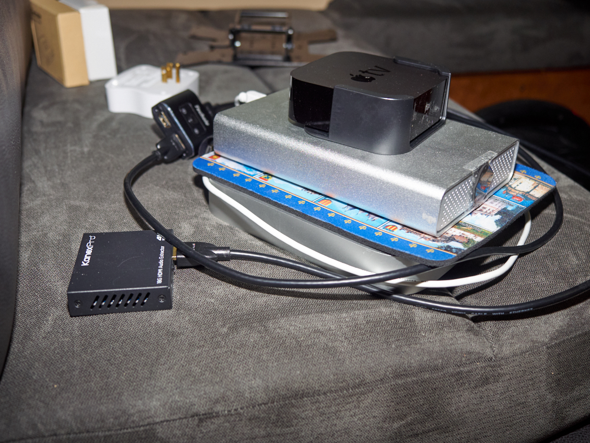
Next up
is the installation of the entertainment system. For
Lance, as with the HiLo, the system consists of a Mac Mini, a
large hard drive with video files, an Apple TV and some support
circuits including an A-B HDMI switch and an HDMI audio extractor.
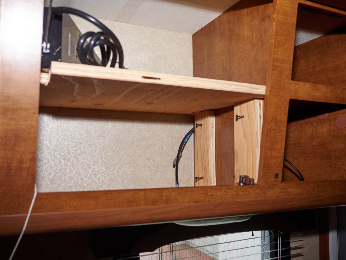
The
entertainment system hardware will be mounted on a shelf
installed in the cabinets. Holes were drilled in the
cabinet walls to allow passage of the HDMI cable that supplies
the display panel. Mounting supports for the shelf were
cut and test-fit into the cabinet.
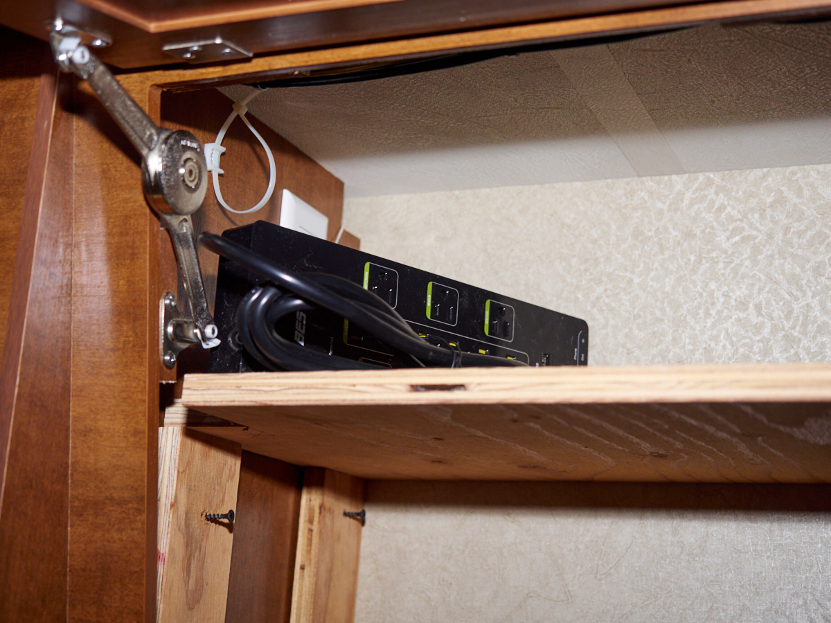
Most of
the entertainment equipment is powered by "wall warts" (small
transformers that plug into a socket). These wall warts
use up more than their fair share of plug real estate thus
requiring a large socket bar to support our installation.
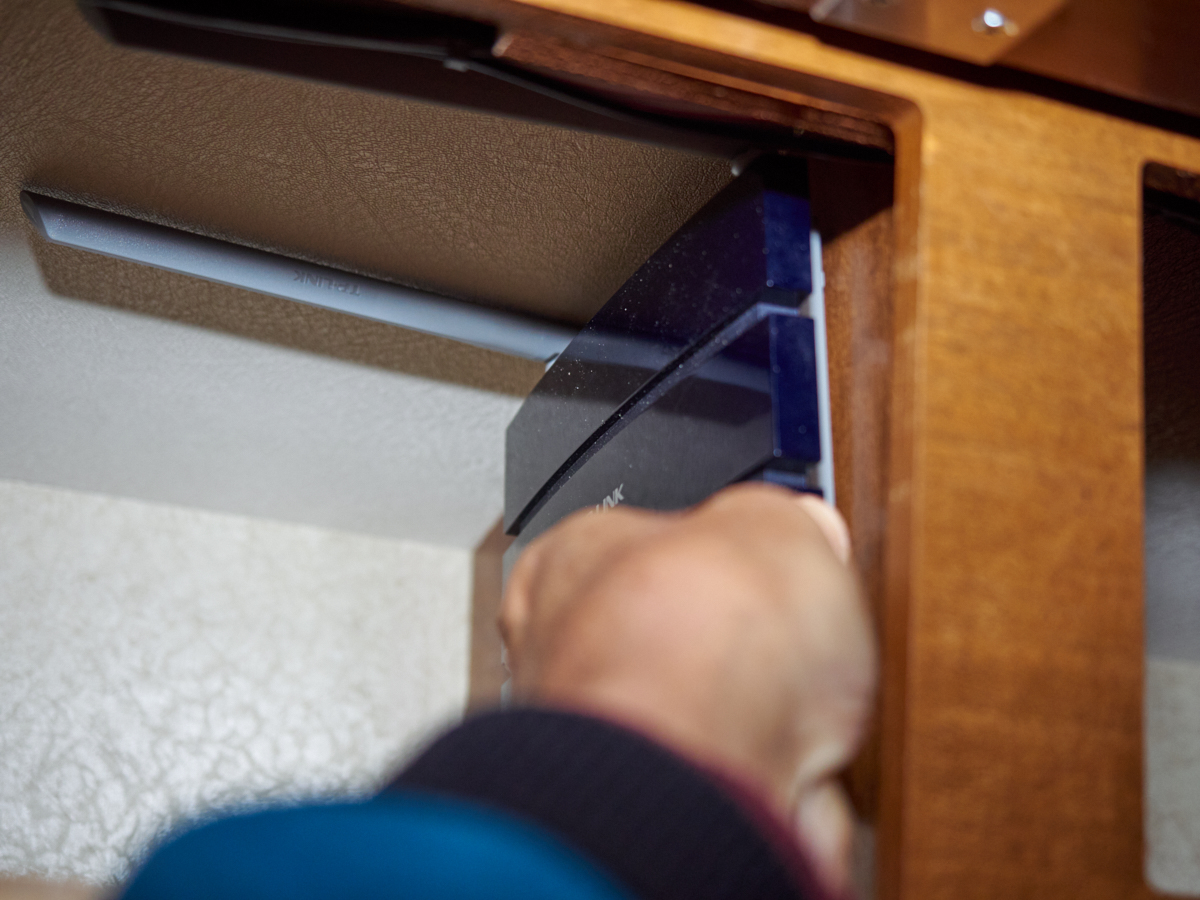
The plan
is to put our WiFi router on one of the cabinet walls, so a test
fit was required to confirm feasibility.
| Previous Adventure | ||
| Trip Home Page |
Photos and Text Copyright Bill Caid 2019, all rights
reserved.
For your enjoyment only, not for commercial use.