During
the purchase process I explained to the salesman that we were
going to "slaughter" the Lance to mount it on Thor. He was
aghast, but claimed he understood the objective. After
all, I did force him to view Thor complete with dirt, brush
scratches and oil stains, so there could be no mistaking our
intentions. I asked many questions about gaining access to
wiring harnesses and plumbing. He and his service team
were very helpful. The photos below describe the
installation of the Seagull water filter and the preliminary
electrical modifications.
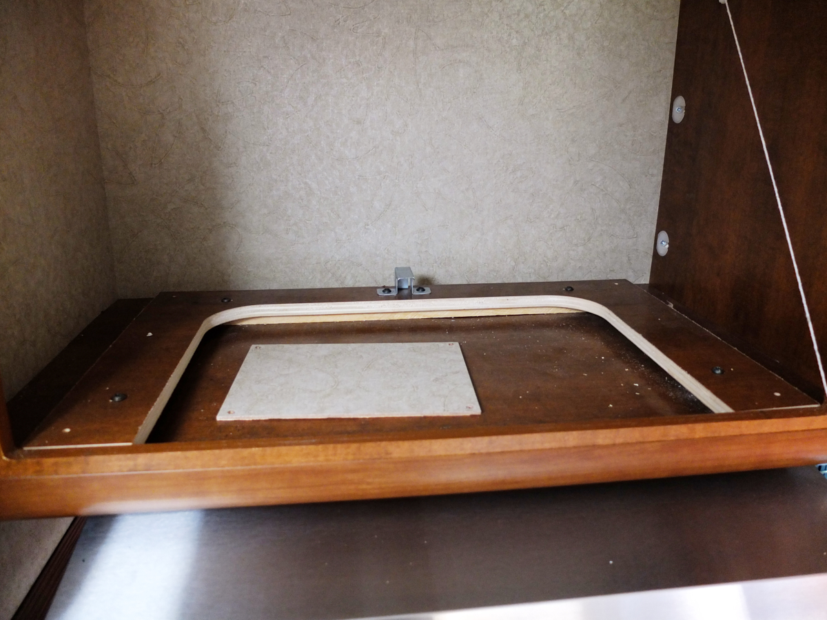
The photos below are what we saw.
To gain
access to a wiring harness, the microwave had to be
removed. Note the latch at the center of the photo above:
this is the rear restraining latch for the microwave to prevent
it from bouncing during transit. The micro was in there
nice and snug; no motion possible.
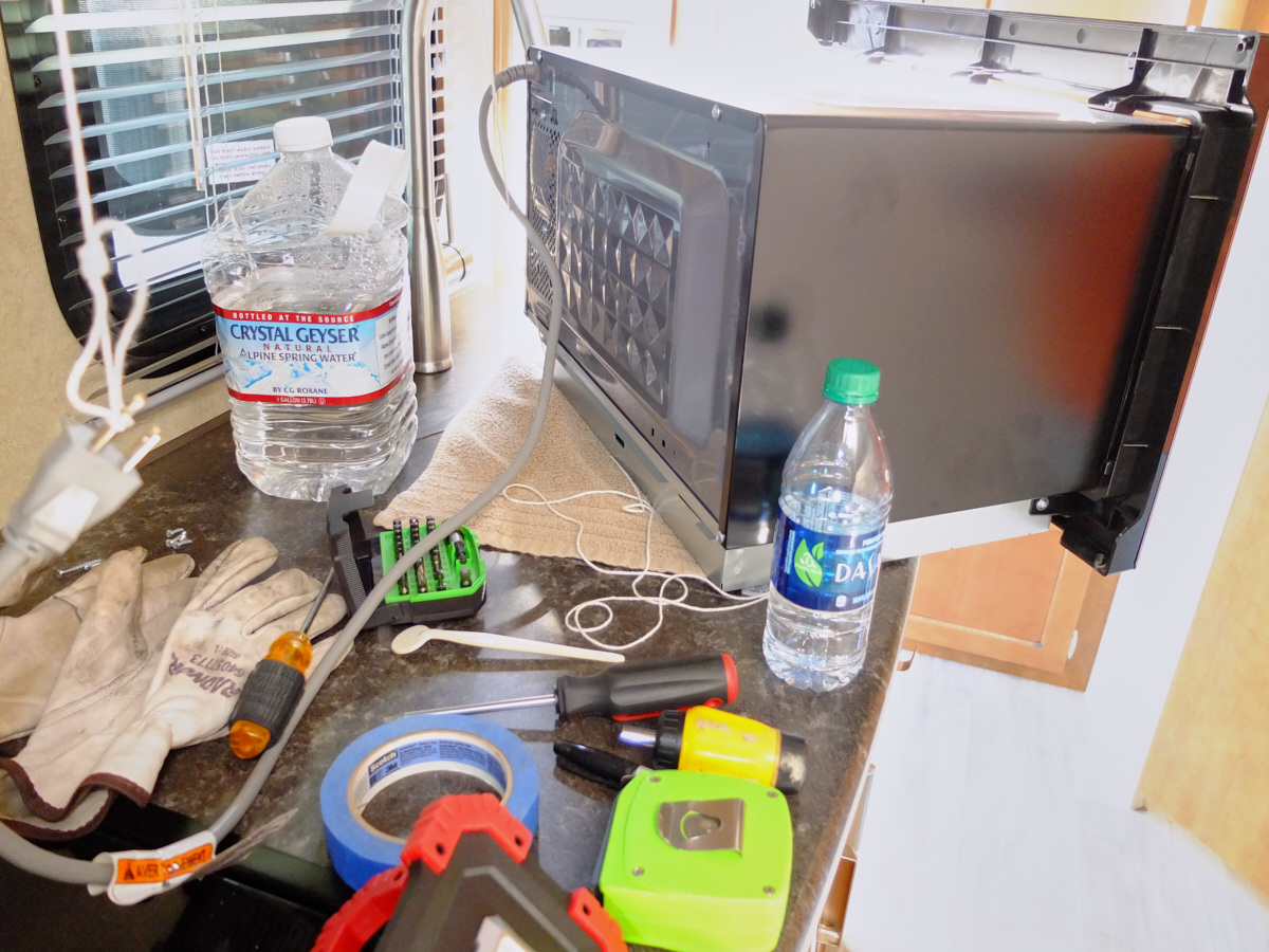
Once the
microwave was out I placed it on the counter to allow access to
the cabinet.
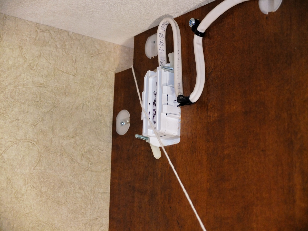
For
whatever reason the plug for the micro was installed in
the microwave compartment but with the plug on the opposite side
of the wall. The wire had to run through the notch at the
top left of the wall. Since the opposite side of the wall
is a normal cabinet, I assume they did it this way to preserve
the look of the cabinet interior.
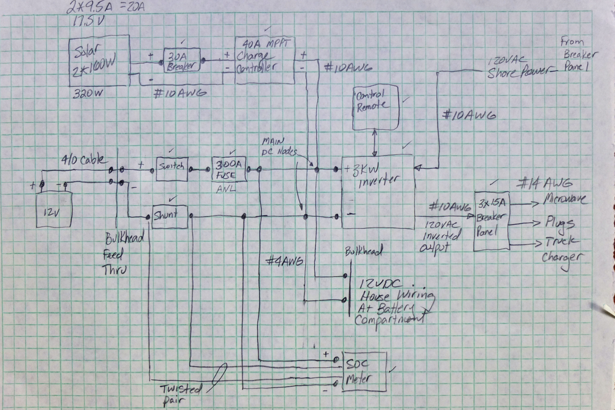
A photo
of my work-in-progress circuit diagram for our
enhancements. Only a few enhancements were planned, but
these required substantial work. Solar would be added as
well as a 3kw inverter with control and monitoring displays.
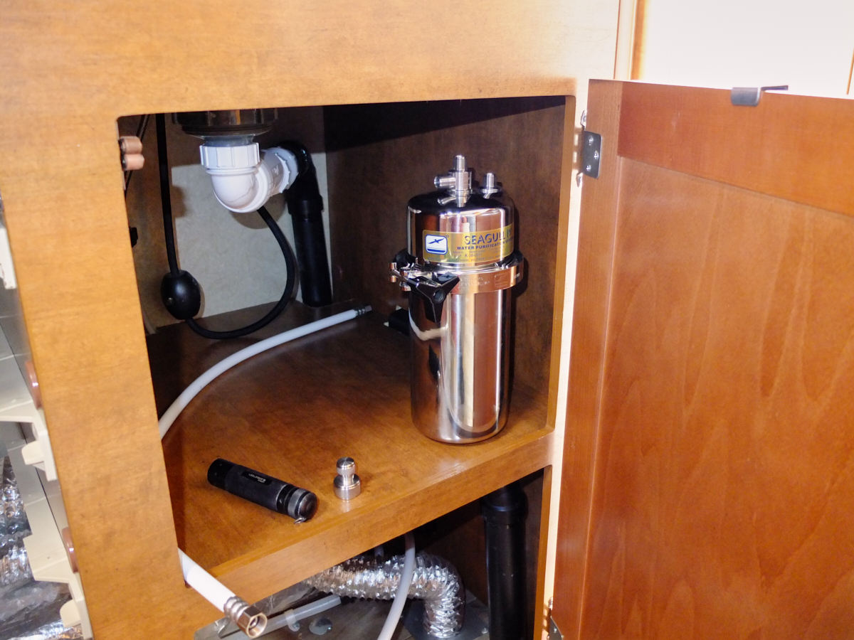
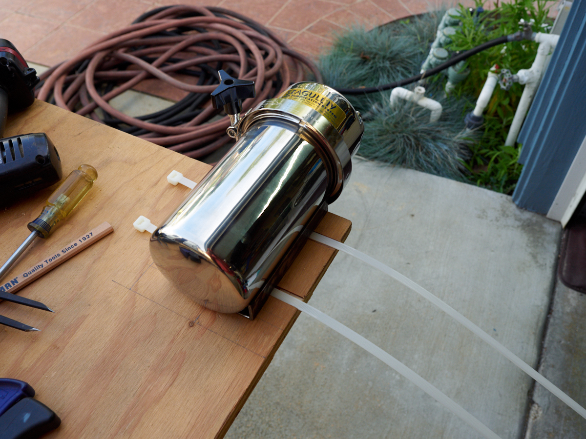
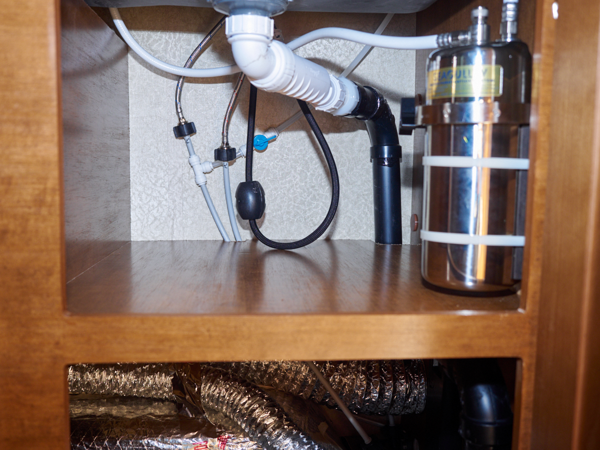
The
water filter finally arrived. This fellow was very
expensive to the tune of $1200. It is a very nice filter
that allows filling the tank with potentially contaminated
water. The water produced is very good tasting. The
filter canister is quite large and requires a robust mount (not
provided). Above, a test fit to prove the filter will fit
in the intended location under the sink.
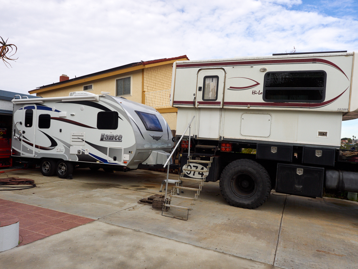
When the
mounting actions are complete, we expect the Thor-Lance
combination to be about as high as the HiLo when the top is
raised. But, the Lance is way, way more comfortable and
deluxe.
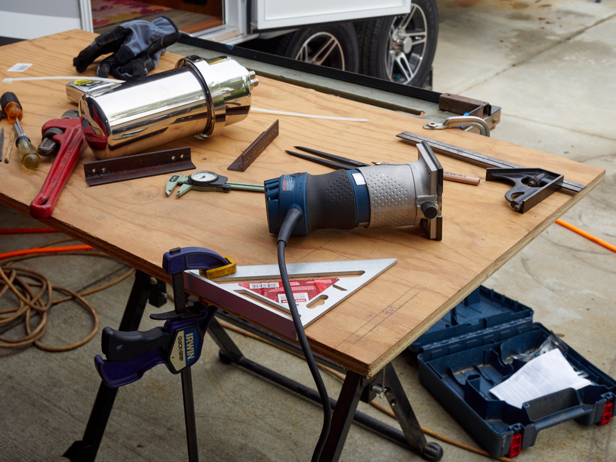
The plan
was to fabricate a mount for the water filter out of
plywood and some scrap angle iron. The parts were
assembled and a plan was devised.
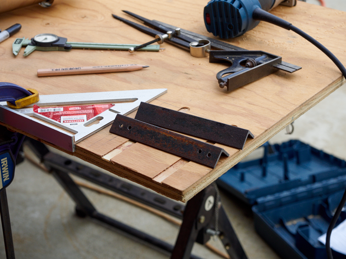
Channels
in the plywood were routed out to allow passage of large, robust
zip ties.
Final
spacings were determined before cutting the mount and attaching
the angle brackets.
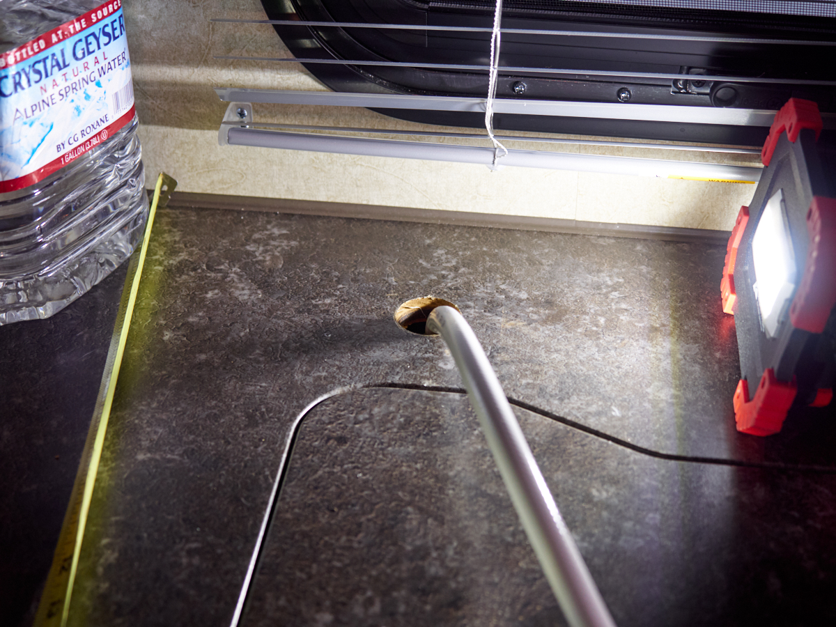
An 1
3/8" hole was drilled in the brand new counter top.
The tap
will be installed in the hole with special gaskets.
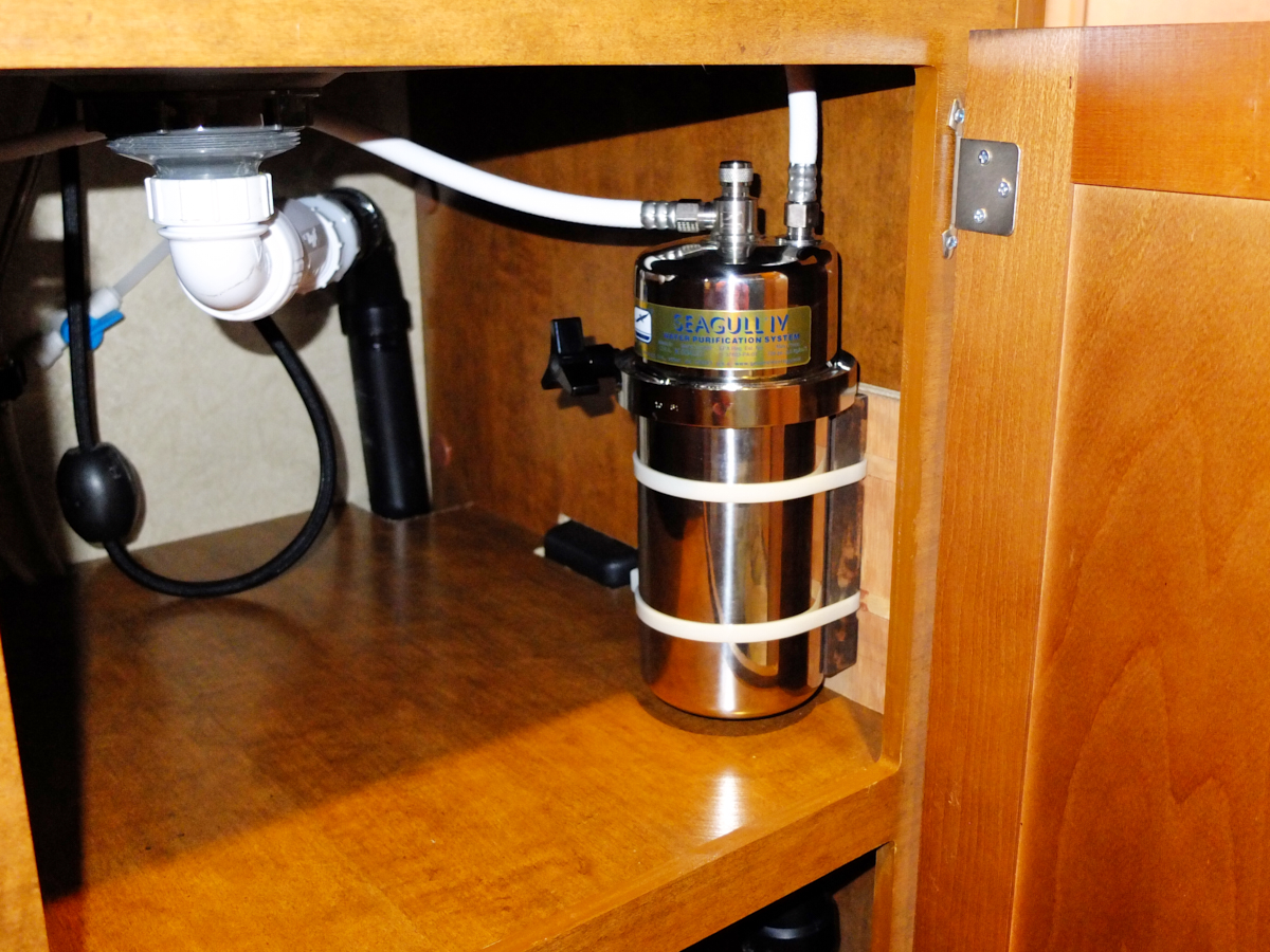
The
filter and mount were attached to the cabinet walls.
We
tapped into the 1/4" PEX faucet supply line using Shark Bite
fittings. These are pricey but work so easily.
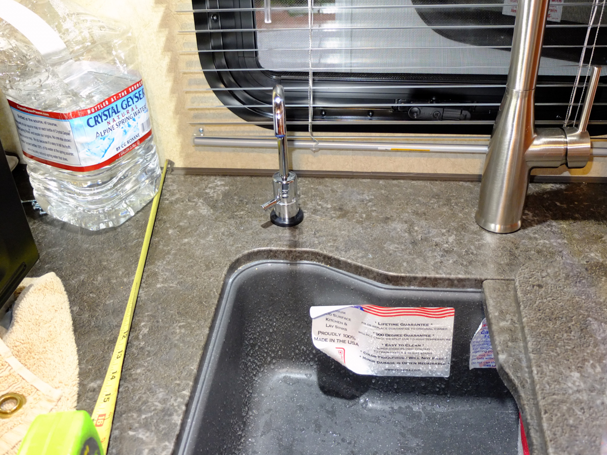
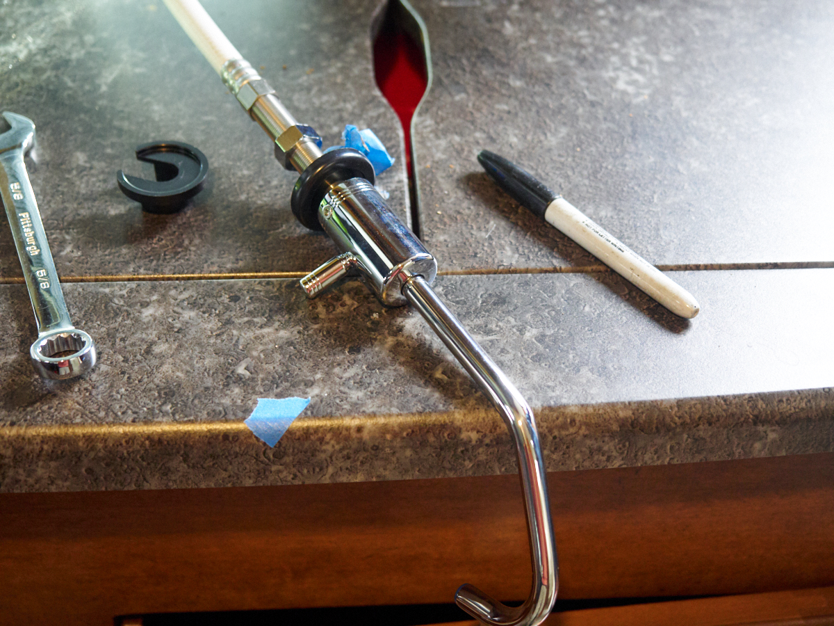
We
placed the tap at a location that makes it look as if it was
intended to be there. With Lance's high-pressure water
system, this tap really pushes the water.
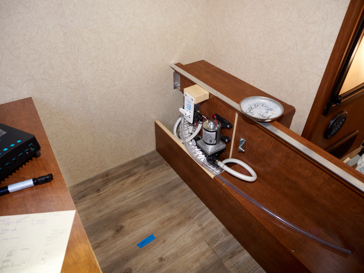
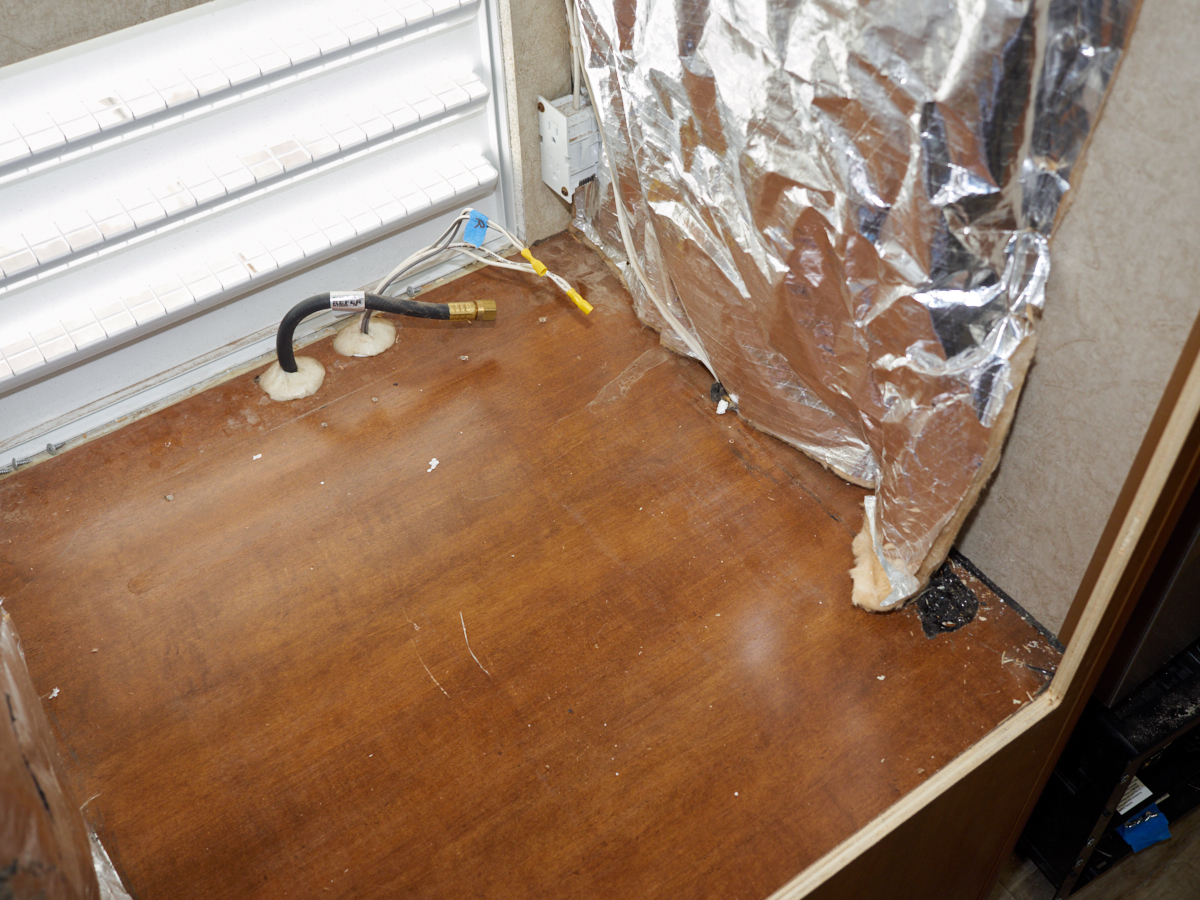
Next up
is to determine the location for the inverter and high current
wiring. The area above is under the bed and is accessible
by lifting the mattress via the gas spring assist
mechanism. The base of the bed has been removed as well as
the gas springs to allow easy access to the area. The 3kw
inverter will go on a mounting board in the area between the
blue tape and the far wall.
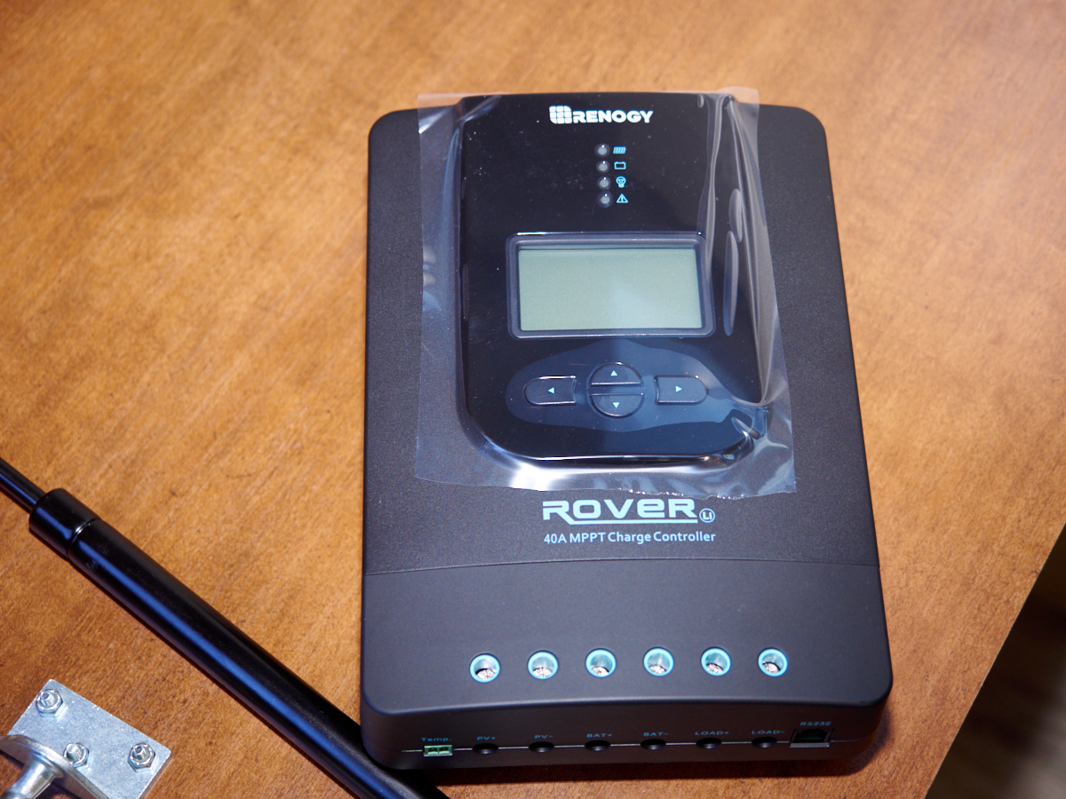
A
special, high-performancec 40A solar charge controller was
ordered. Since this unit has a voltage converter, it is
big and has large heat sink fins and will require a vertical
mounting location. I intend to mount it on the inside of
the exterior wall near the water pump.
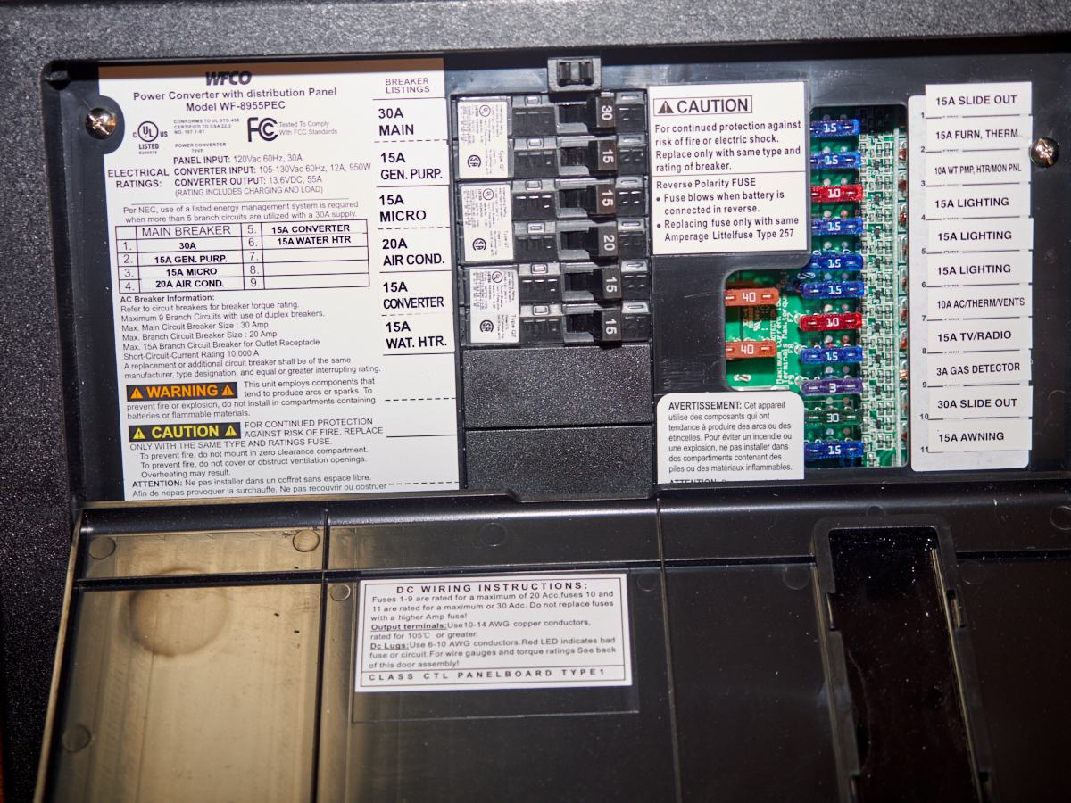
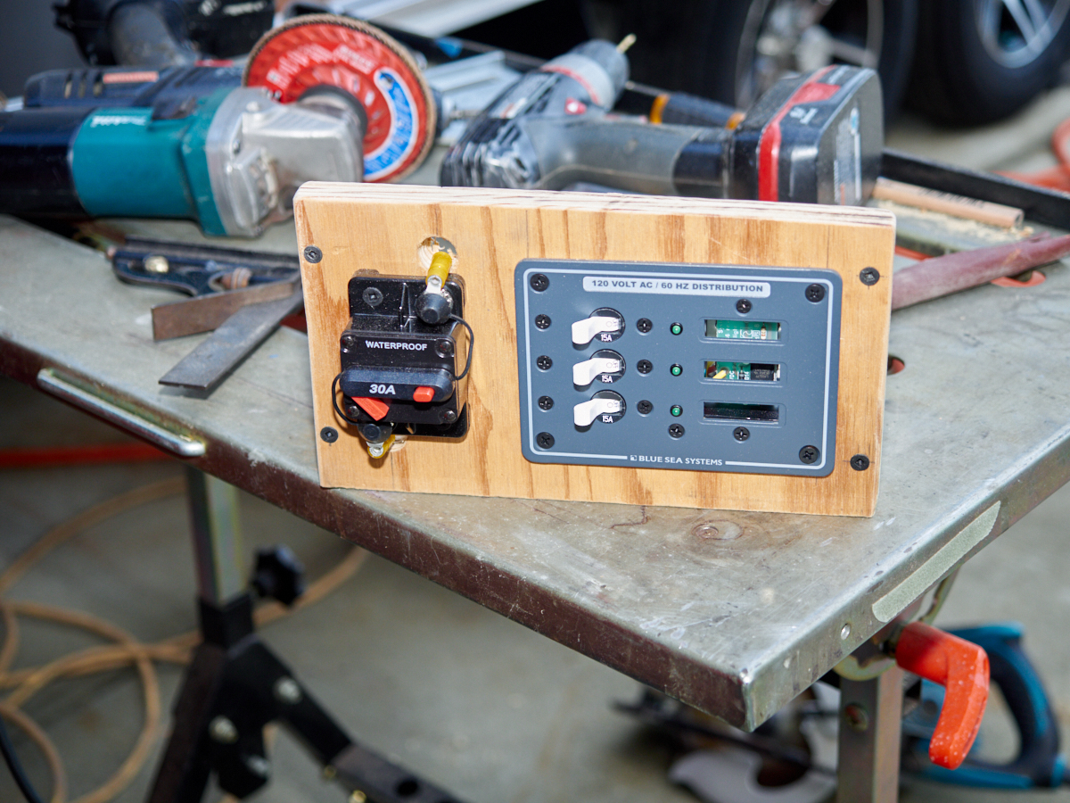
A shot
of the circuit breaker allocation of the existing panel.
We intend to migrate the circuit breaker functions for the
general purpose and microwave circuits to an AC subpanel that is
driven by the inverter. We will also split out the
refrigerator line from the general purpose and put it on its own
breaker. The Converter breaker will be used to power the
inverter/converter. And, if necessary, we will parallel
two of the defunct breakers to serve as the power for the
inverter/converter (it can use up to 30 amps).
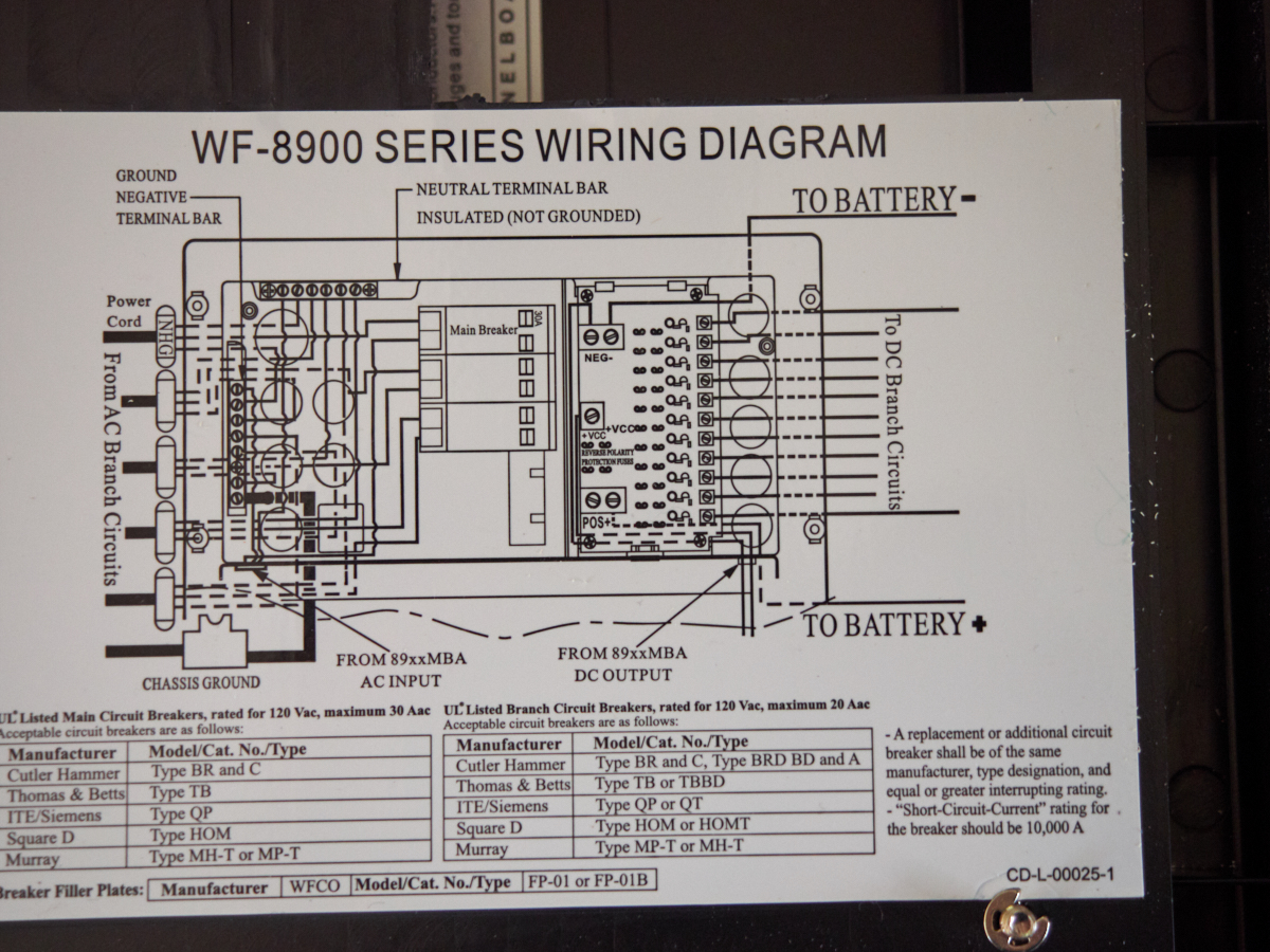
The
physical wiring diagram of the existing system.
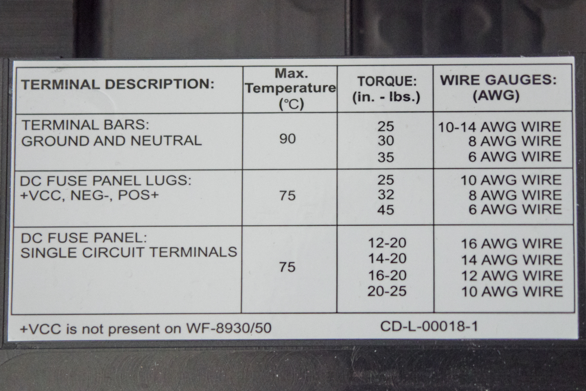
Use,
temperature, torque and wire requirements for the DC side.
The
existing breaker panel before I tear into it.
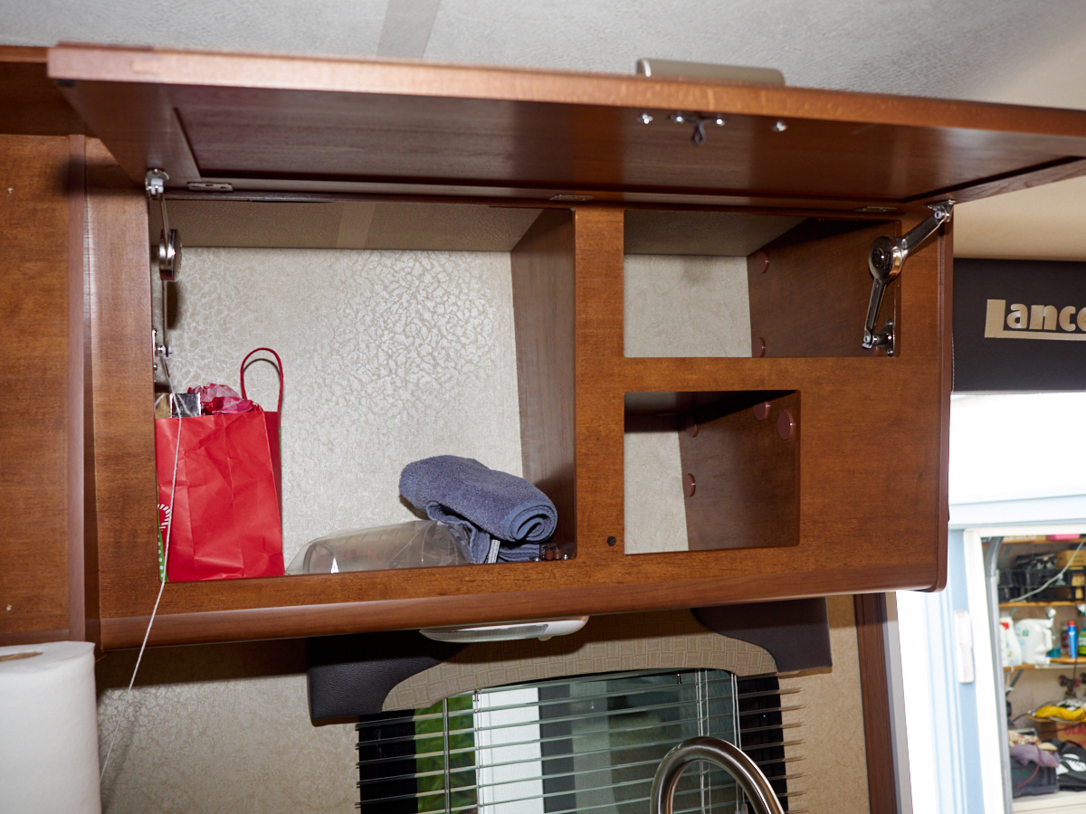
The
upper right side of the cabinet will hold the electronic package
for the home entertainment system. We will extend the
microwave power line to power the system.
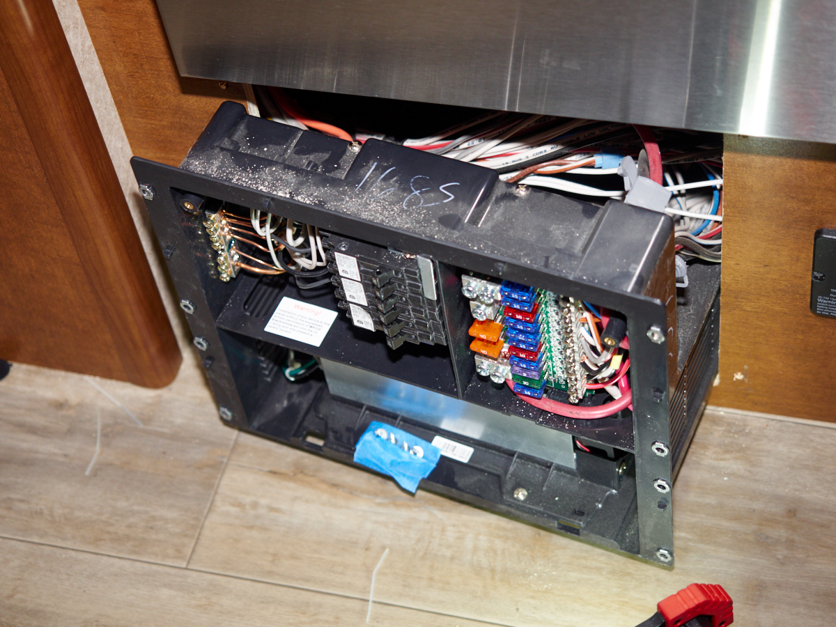
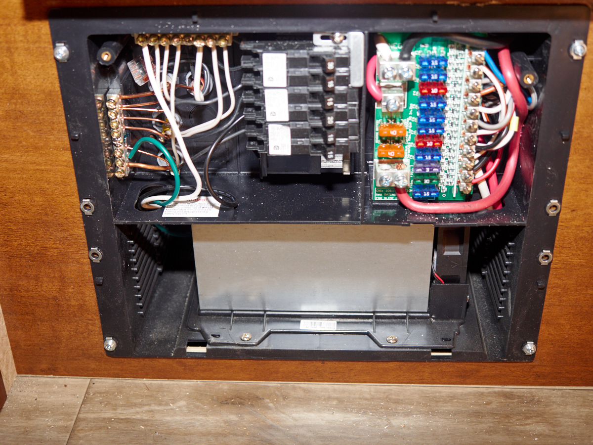
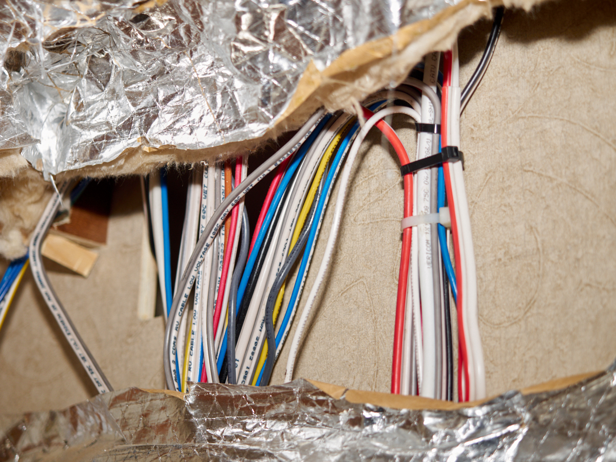
Removal
of the combined AC/DC panel reveals the huge mass of wires.
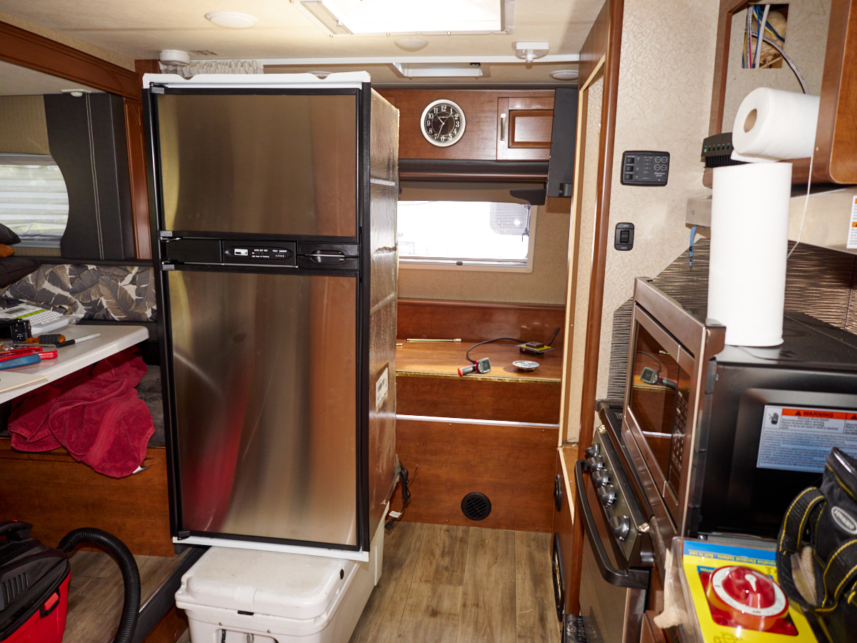
To gain
access to the required wiring bundles and passage ways, the
refrigerator and microwave had to be removed.
The
refrigerator cavity had insulation on the top and sides.
| Previous Adventure | ||
| Trip Home Page |
Photos and Text Copyright Bill Caid 2019, all rights
reserved.
For your enjoyment only, not for commercial use.