We had been waiting for a bunch
of parts to come from our vendors. As it is with most things,
they did not arrive in synchrony. So, we had to wait until we had
the required parts before moving on to the next set of actions.
The original plan was to have the high-current DC switches and fuses
contained in an external tool box. This box would also provide a
home for the 30 amp electrical cord and other utilities. The tool
boxes were ordered in October, but I needed various sizes that were not
commonly available. After much web work, I found that San Diego
Trailer Supply would order the required boxes. The only bad news
was that the boxes would not arrive until "January". On December
30th, they called and stated that the boxes had arrived and that I had
to come pick them up. A whole pallet of boxes, about $3K worth as
it turns out. Since the mog had leaking brake seals due to a
driver error causing an over-heating situation (all I will say is that
I was not driving), we secured the 1017, attached my flatbed trailer
and headed to get the tool boxes.
The photos below are what we saw.
We had a small "accident" with our
tire crane. During testing, I discovered what I consider to be a
design flaw in the control switch. Basically, the switch is two
push buttons. No problem there, but the issue is that the
direction control solenoid valve on the hydraulic motor can change
directions nearly instantly. Meanwhile, the pump motor is ramping
down causing the boom to whip back and forth. With a 400 pound
tire/wheel combo at the end of the cable, that would produce
interesting results. The problem only occurs when you are
retracting the cylinder. I attempted to rework the switch, but
during testing, a small bit of stripped insulation from one of the
wires I was working on got caught inside the switch mechanism. On
the next test run, the motor stuck in the "on" position, driving the
cylinder into the stop. But, since there was another few inches
of travel left on the cylinder, it did a great job of bending the
frame. Make no mistake about it, hydraulics are strong. The
solution to the problem, aside from unseating the lodged debris from
the switch, was to fabricate a switch assembly that would prevent the
issue from happening again. And, since I was at it, I folded in a
switch for the winch motor as well and placed it on the same control
dongle. I also added several safety circuits to prevent things
from getting "sideways" again. After the construction and
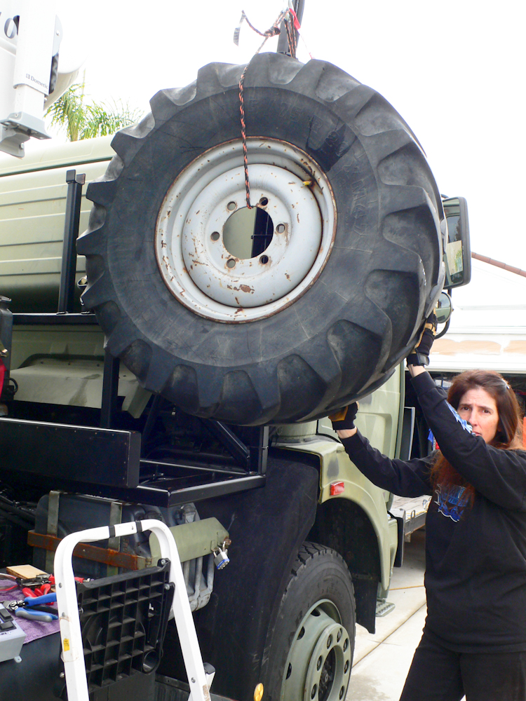
installation was complete, we needed a full-weight test. The new
control dongle is the gray box at the extreme left of the photo, at the
bottom and is only partially visible. Kathleen assisted in the
test but was none-too-happy about being close to a full-size XM47 on
the end of the winch cable. Note the expression on her face.
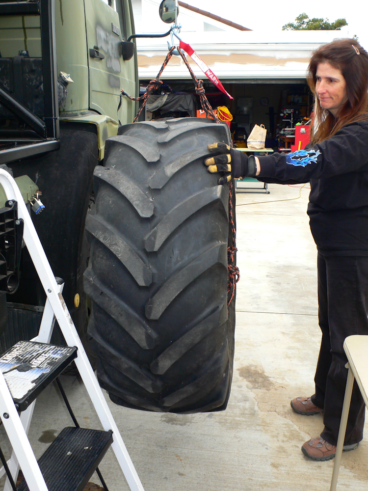
All components of the system
performed as designed and we were both pleased. Kathleen was
especially pleased when that big tire was close to the ground and not
over her head. The crane picked up the wheel/tire combo without
missing a beat.
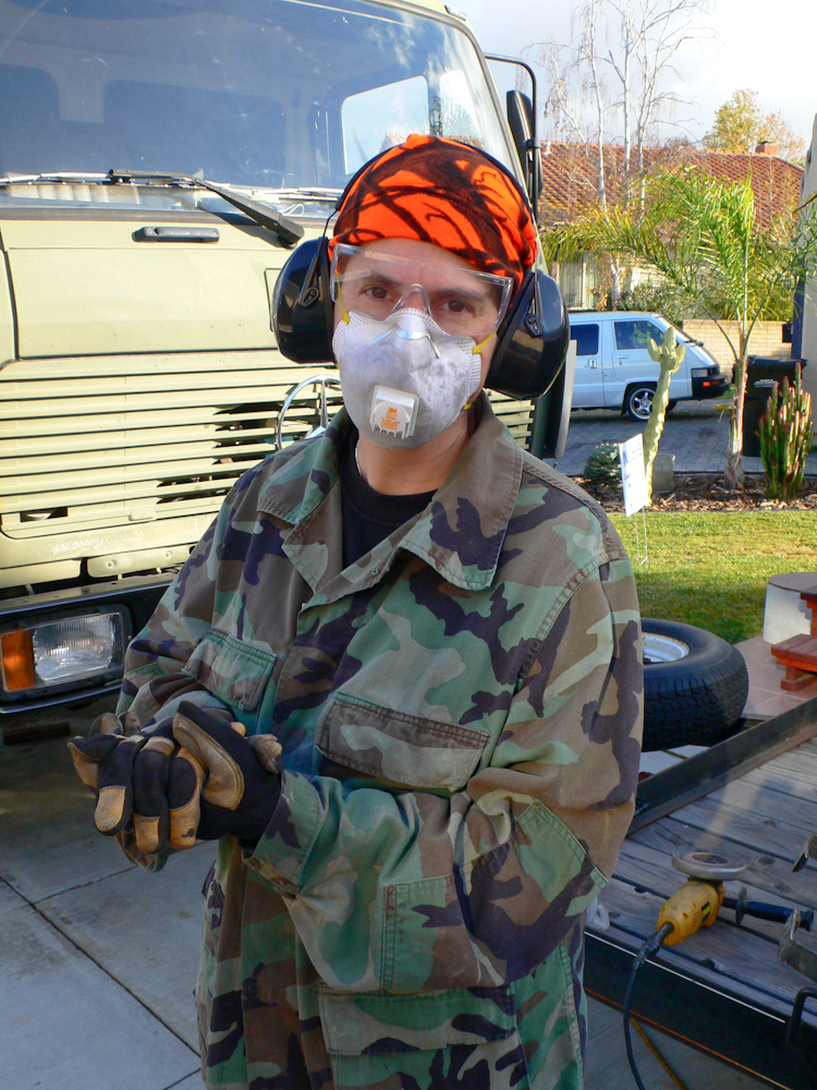
We had to install flooring for the
tire crane area, but before we could do that, we had to paint one of
the can racks. Above, Kathleen suits up for a bit of wire wheel
work in preparation for painting.
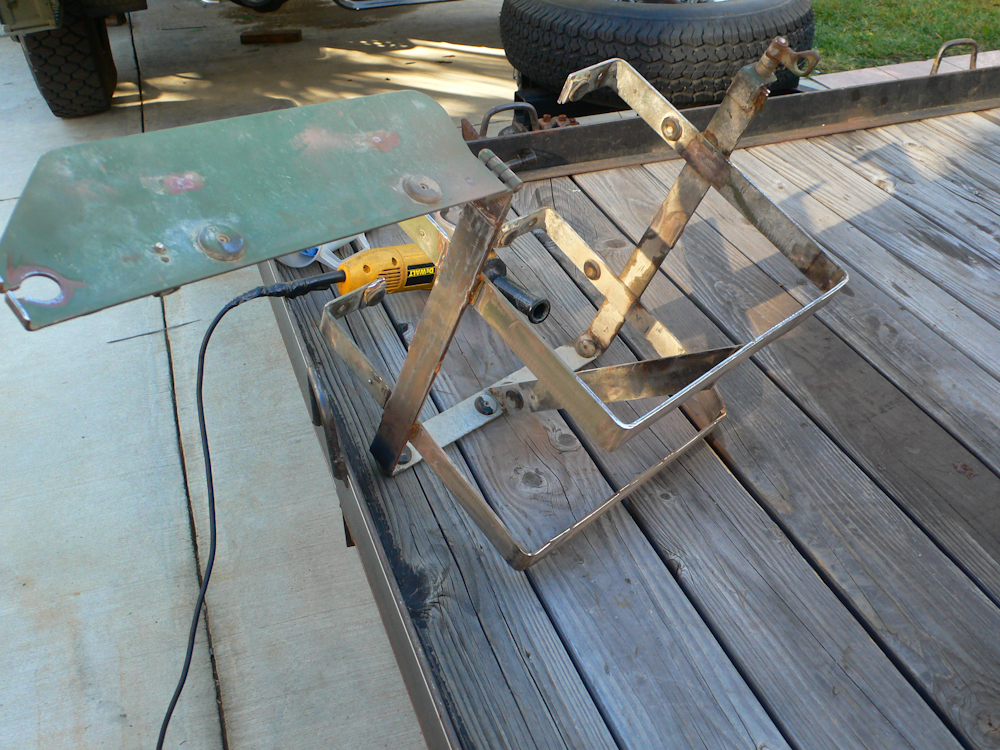
The can rack is a standard-issue
unimog rack that I got from Rob Pickering. The frame needed a bit
of reinforcement, but was generally in good shape if you like
olive-drab. The color scheme for the 1017 is black and white, so
a repaint was in order. Above, Kathleen got all the old rust off
in preparation for priming and painting.
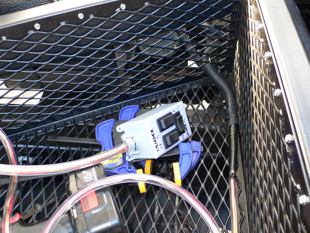
Sometimes, I do things that I do not understand. I am not sure why I did not take a "real" photo of the crane control dongle, but this is the best I have. The solution to the whipsaw effect was to separate the direction control from the motor control. All that was required was to select the direction of the valve and hold it constant while the pump was in motion. That was a costly discovery.
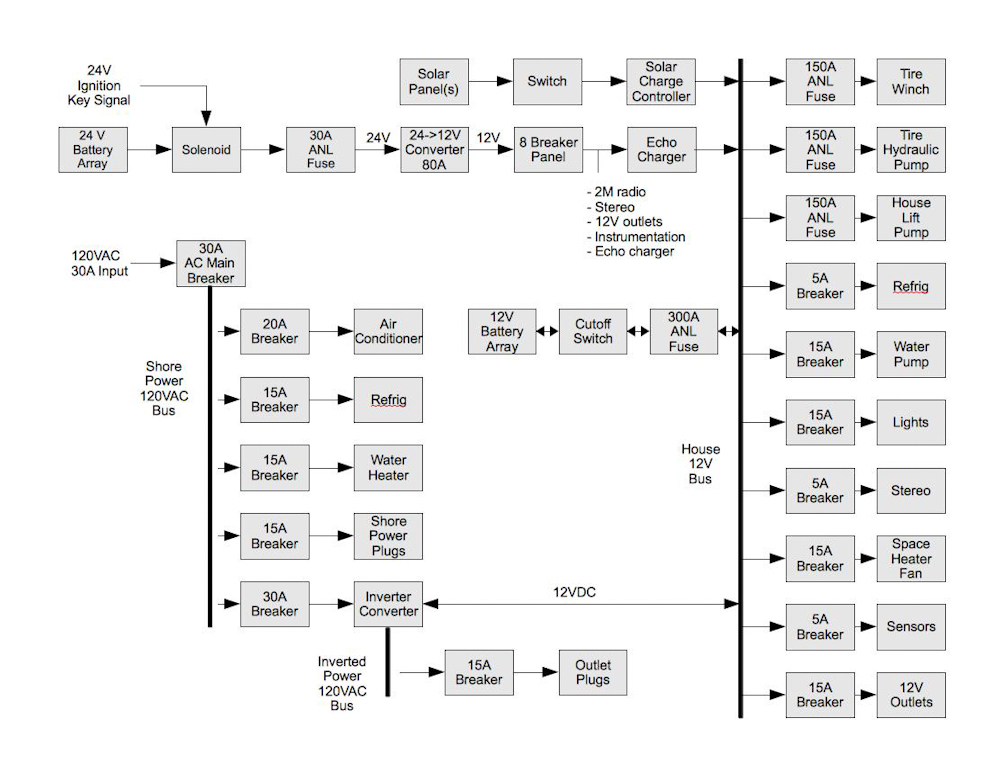
The electrical system for the 1017
is somewhat complex. There are lots of "things" and of course,
the truck itself is 24V and the camper is 12V. And, most
electronic components available here in the US are 12V, so a 24->12V
converter will be required in the cab. But, I include the
diagram here for reference to get a feel for the scope of the effort.
My inverter had finally
arrived. I ordered one from a discount marine store on the web
and it arrived damaged. 3 weeks were expended "discussing" the
issue, but it was finally resolved. My response was to order from
a different vendor that was more reputable. That unit, a Xantrex
2KW device, arrived with no damage. The planned installation area
was under the couch area. But, upon inspection and much to my
dismay, the area was crowded with plumbing. To install the
(heavy) inverter in the correct location would require removal of the
existing plumbing and a re-routing of the pipes. Simple things
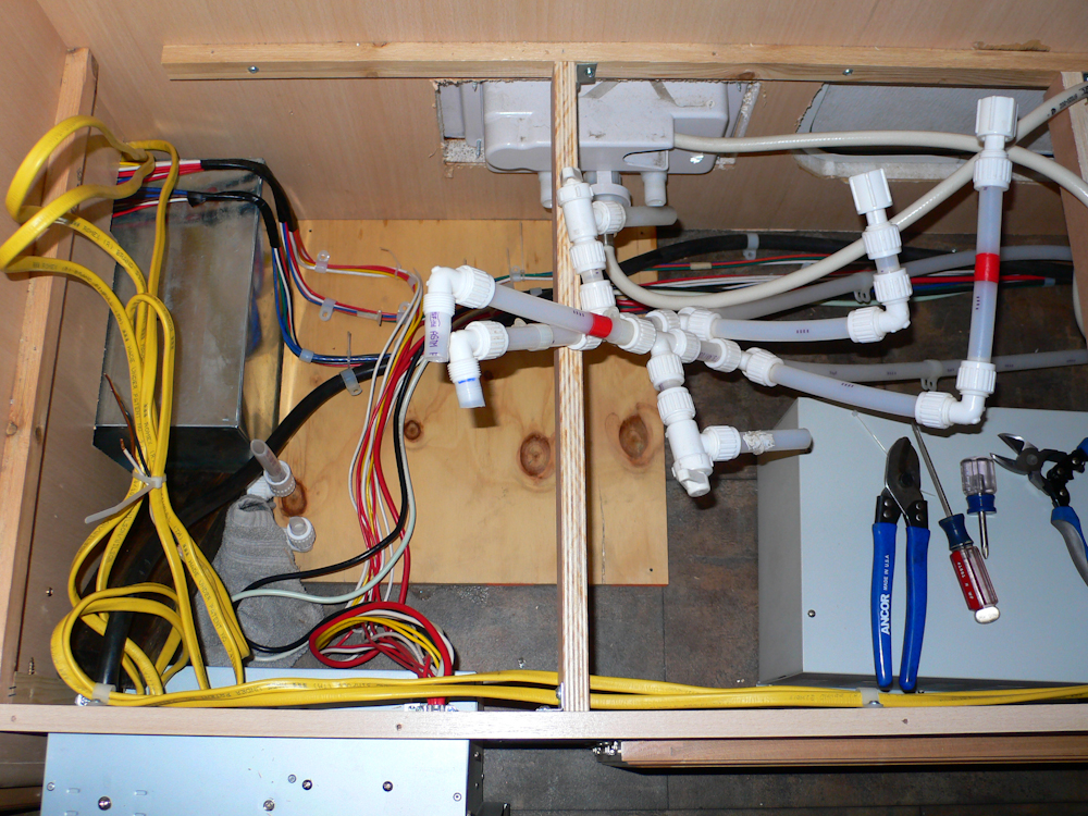
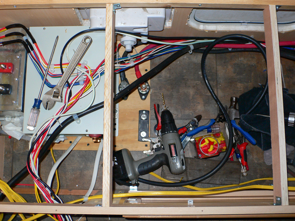
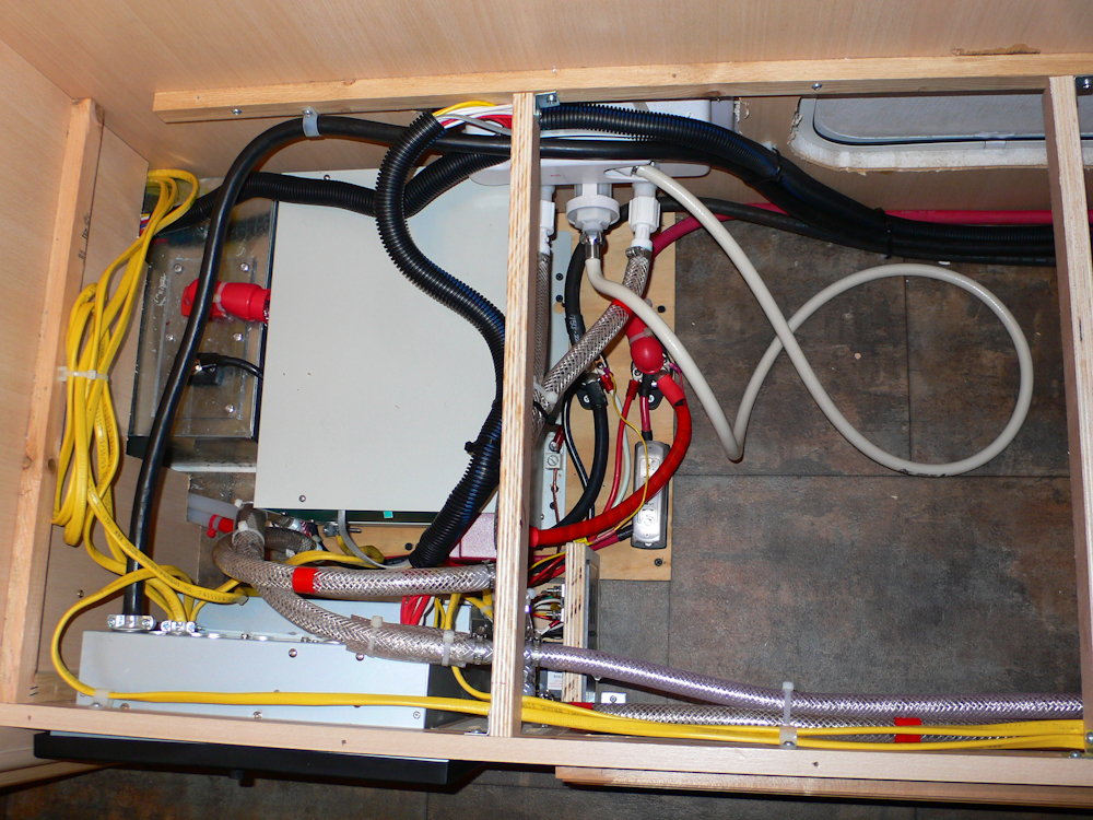
are never simple. In the photo above, you can see the PEX pipe
that was used in the Hi-Lo camper. The inverter is the gray box
at the right of the photo with the tools on it. The plywood panel
will serve as the base for the inverter and the mount for the high
current power posts. The sheet metal box at the left is the wheel
well for the trailer.
The guys that assembled this
camper did not even put the water pump in straight. The angle
above is the way it was. That, of course, will change in short
order. One of the other side effects of their "design" was that
the space under the couch was unusable for storage. So, there
were multiple reasons for re-plumbing the cabin. Plus, as I
planned the effort, I discovered that pex fittings are not commonly
available. The ones that are available are very expensive, $6+
per fitting and I could not find a local vendor for the pipe
either. So, the pex has gotta go.
I got my tubing cutters out and
nuked all the pex pipe. The pipe will be replaced with standard
reinforced plastic tubing, commonly available at hardware stores.
There were a ton of wires back there and none were labeled. Great
care was required.
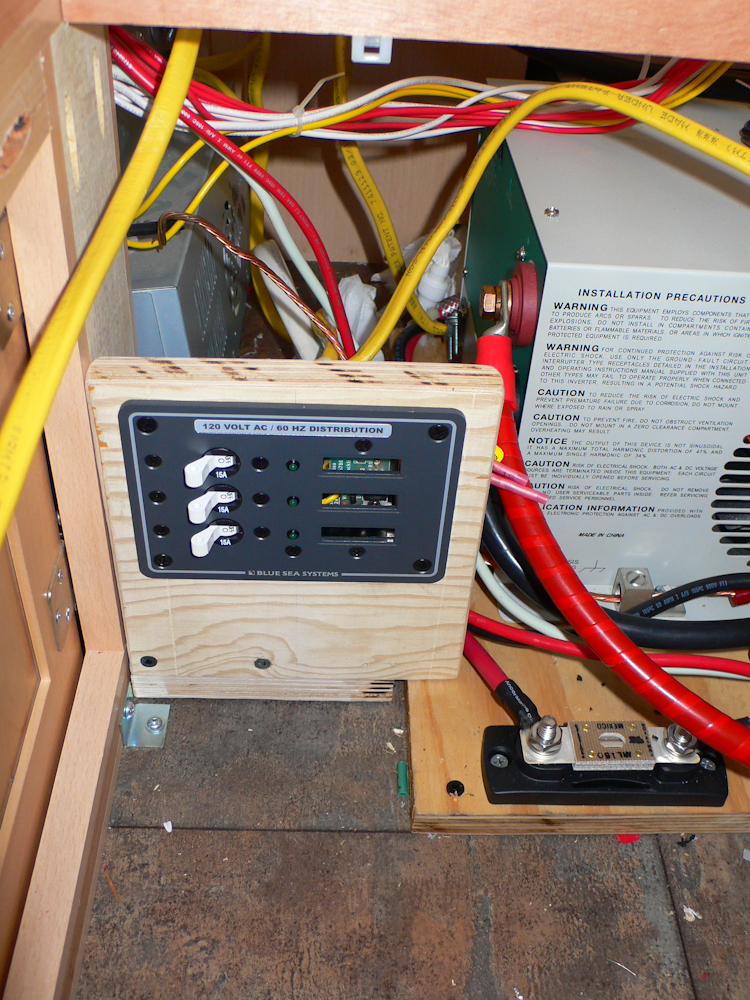
Happily, I was able to re-use the
AC wiring and for whatever reason, the AC circuits were much better
designed than the plumbing. Installation of the inverter was
straightforward but required creation of an AC sub-panel to provide
circuit breakers for the inverter circuits. An expensive trip to
West Marine got me what I needed. Note the 150 amp DC fuse in the
photo above. That fuse is for the house hydraulic lift pump
motor. Their original design had no fuse or circuit breaker on
that high current line!
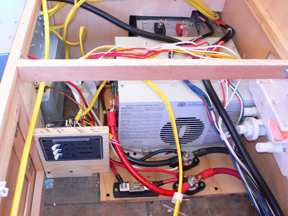
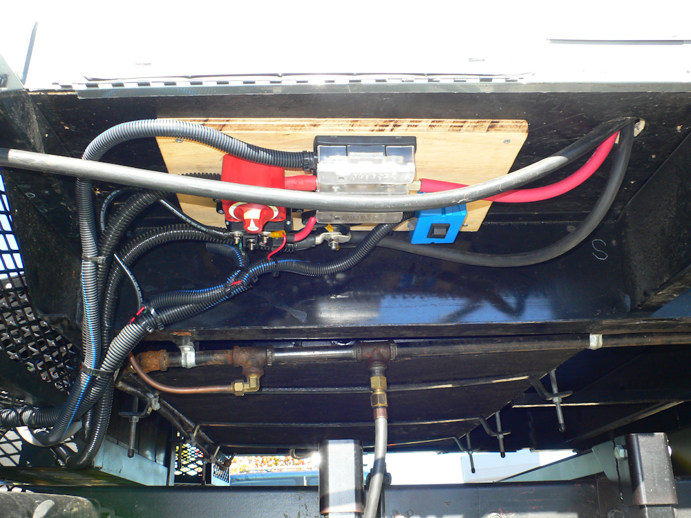
The house lift pump lines were run
from the power posts around the front of the inverter to a pair of
feed-throughs visible at the top of the photo. The pump is
mounted in the wheel well on the other side of the feed throughs.
In the middle of our efforts, the
tool boxes arrived. Since the mog had brake issues, and I have no
other truck except the 1017, we had to suspend our efforts in the
camper to get the boxes. Once things were secured, we lowered the
top. That action required electrical completion of the DC
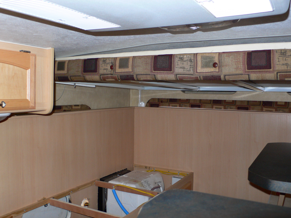
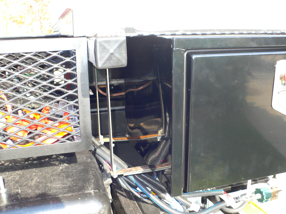
circuits. Once the top was lowered, I took a few photos of the
inside to show clearance of the components.
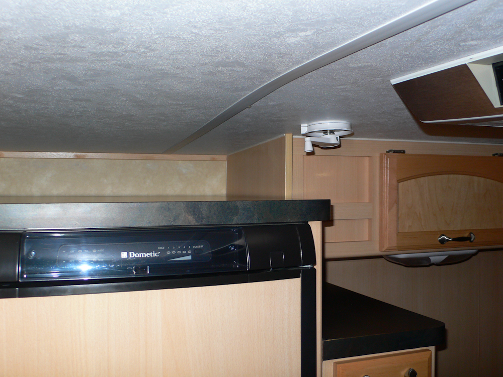
There is still some room left
above the refrigerator, so I may build a shelf or cabinet there.
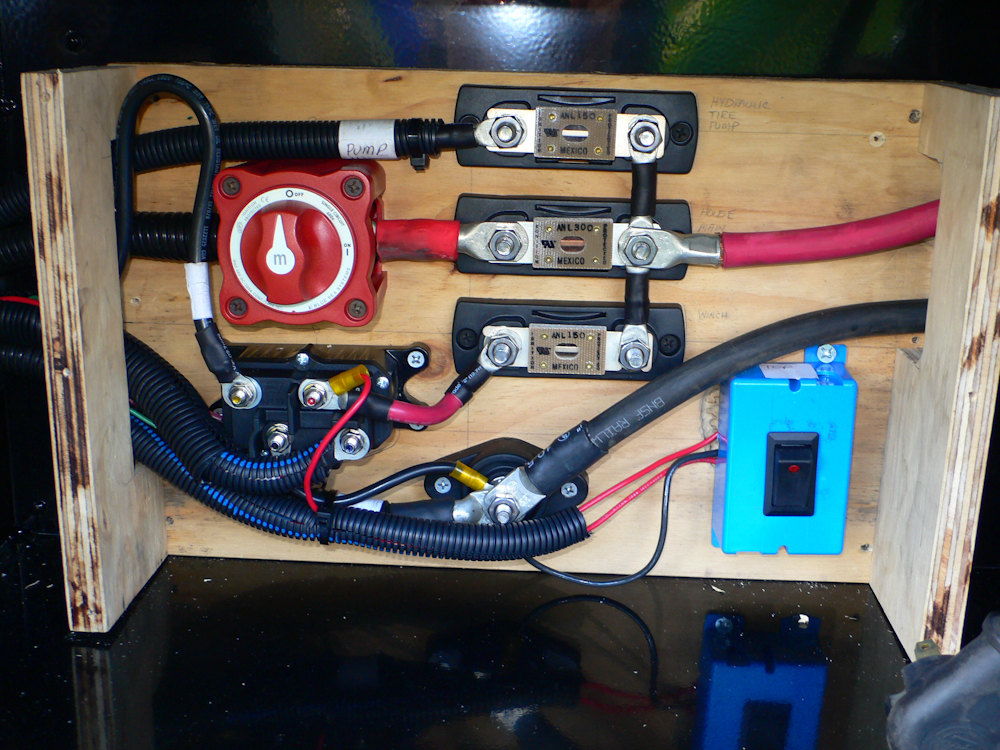
Once we had our tool boxes, we had
to "undo" some of our electrical controls. The board above was
designed to fit inside one of the tool boxes to provide both physical
and weather protection. This board had to be disassembled to move
to the next step. Interestingly, initial construction was
required to test the tire crane, so no effort was wasted.
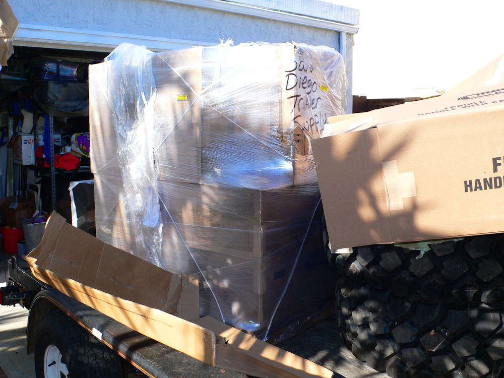
There were a whole pallet of tool
boxes. In the shot above, I had already removed one layer of the
pallet to inspect the boxes.
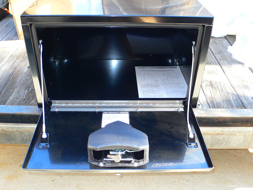
The boxes looked good: robust and
the sizes that I ordered (always a nice gesture), so we moved ahead
with fabrication of the mounts.
The boxes were intended to fit
between the cross members on the camper, outboard of the main
frame. Attachment straps were fabricated with threaded ends
added. The photo above shows a test fit. We rejected this
design and came up with an alternative that had less offset between the
box and the descenders.
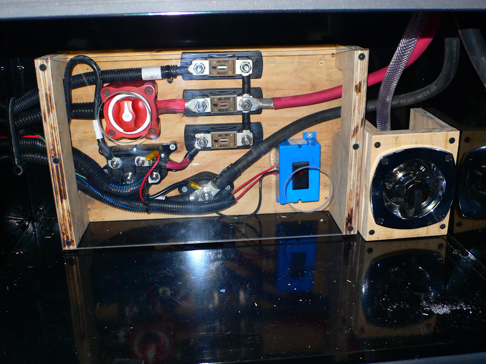
Once the box was satisfactorily
installed, we could then proceed with the balance of the electrical
installation. Stand offs were added to the mounting board to
provide an attachment point for mechanical protection of the
components. The blue switch is the "crane enable" switch to
prevent a damaged dongle from engaging the winch or pump
unintentionally. Ooh,that would be bad.
Ingress and egress holes were cut
into the tool box to allow routing of the cables into the box. A
Plexiglas cover was cut, drilled and installed. Note the access
holes for the 2 switches. In addition, the external water
connection was added to replace the stock connection.
Once the tool box was in place, we
could finish the wiring above. All the wiring was sanitized and
placed in looms. The new plumping is visible at the bottom of the
photo. All things being equal, I would have preferred to not mix
plumbing and electrical for obvious reasons. But, to meet that
criteria would have required a massive re-do of the whole system.
So, we did it with care and checked our work multiple times. But,
one thing for sure, if a hose were to burst or a connection were to
come loose, it would be very interesting.
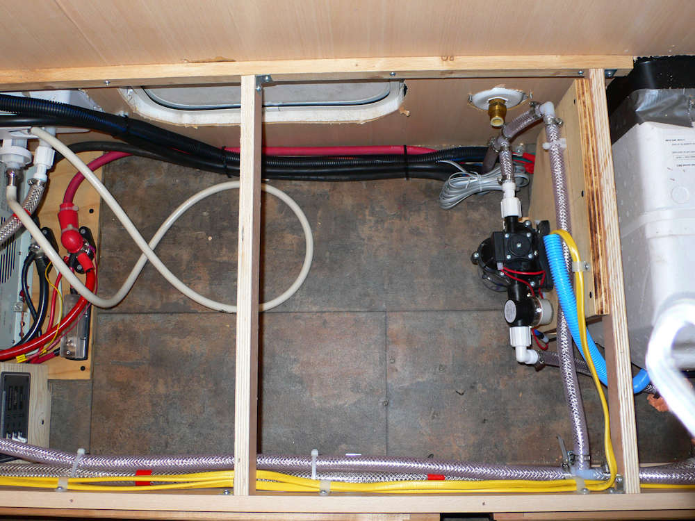
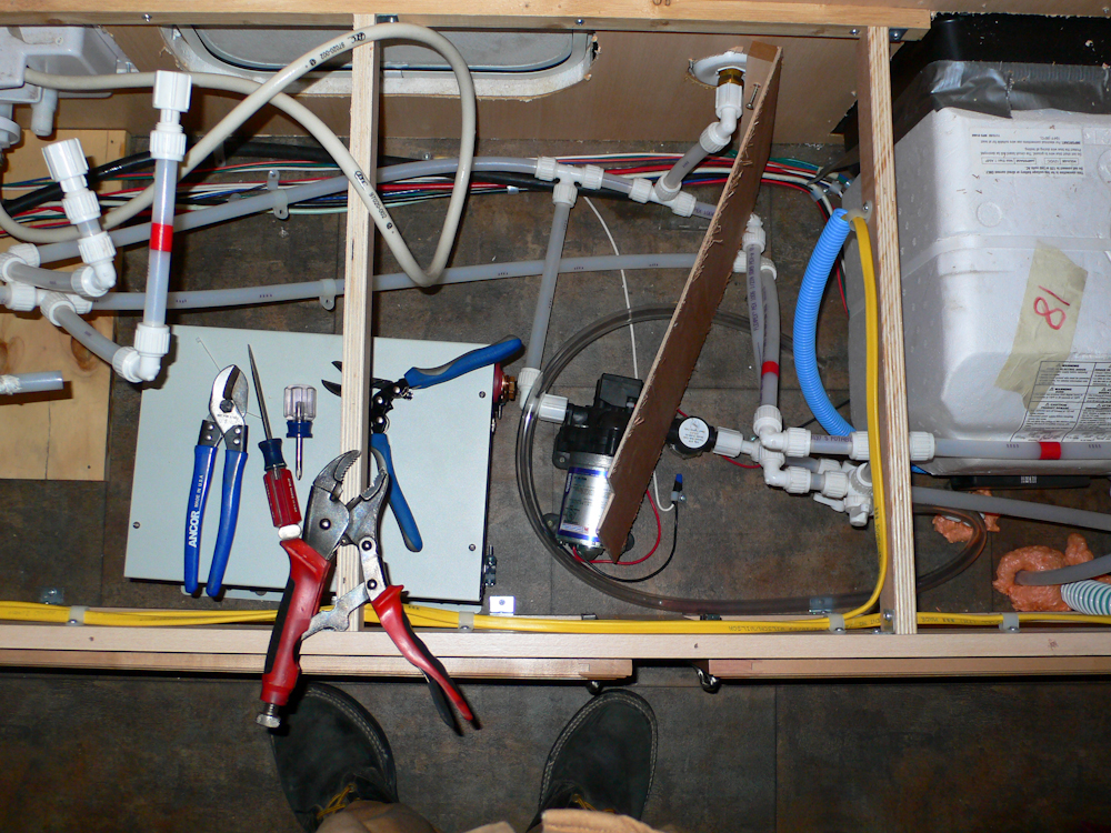
The right side of the compartment
is visible in the photo above. Note that the water pump has been
mounted vertically to provide more room. Also note that the old
water ingress point has been decommissioned; the old fitting did not
have a pressure reducer and therefore you had to add one outside each
time before use. My ingress fitting has a built-in reducer
preventing potential mistakes. I just have to remember to NOT use the
old fitting.
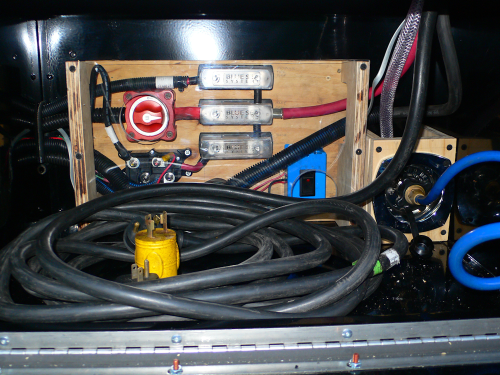
The final tool box configuration
with the coiled 30 amp cable stowed in place. Also, the shore
water hose was installed and tightened. This whole segment was a
ton of work.
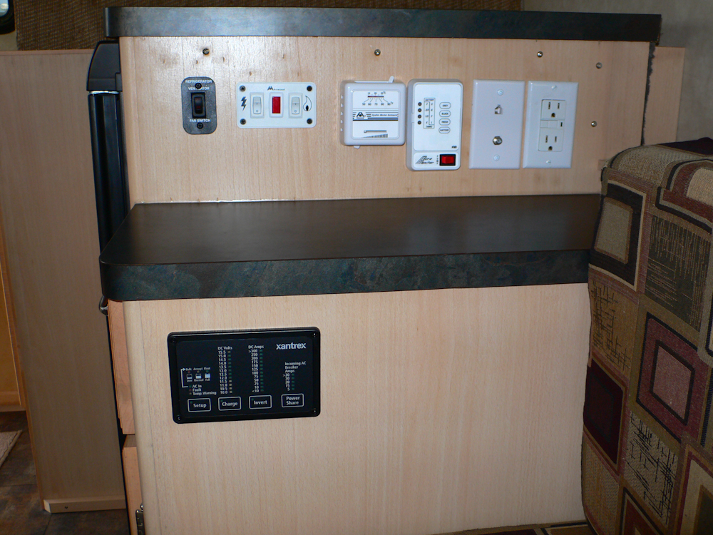
The final act was to install the
remote control/monitor for the inverter. There was just enough
room behind the face of the cabinet to install it without generating an
interference with the drawer.
| Previous Adventure | ||
| Trip Home Page |
Photos and Text
Copyright Bill Caid 2011, all rights reserved.
For your enjoyment only, not for commercial use.