We made good progress in
the first 3 days of our effort. As our comfort level with the
specific actions improved, the rate of progress increased. During
the next 2 days, the sub-frame members were fabricated and a test
fitting of the camper on the truck frame was achieved. All of the
photos below were shot with my little Lumix camera which is 4 years
old, so the photo quality is somewhat lacking on some of the shots.
The photos below are what we saw.
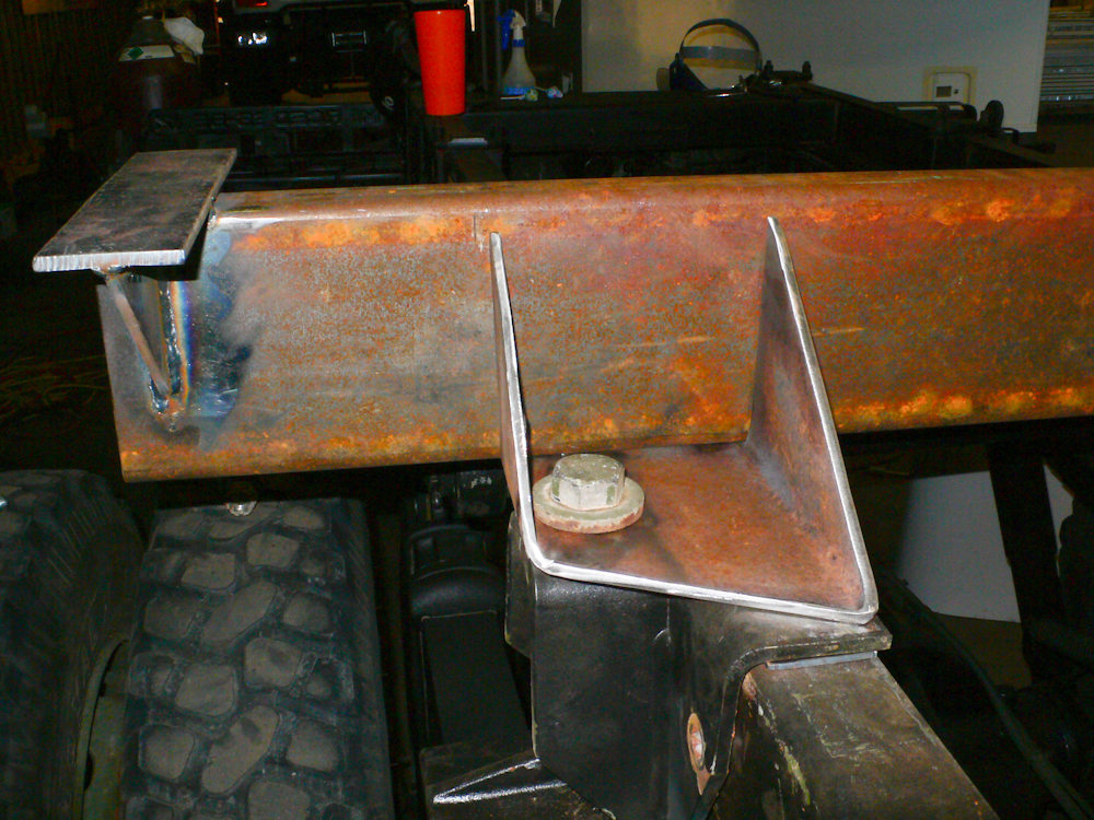
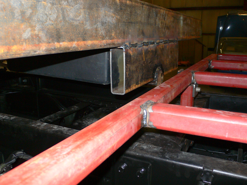
The fixed cross member
was the first beam constructed. We used 2 x 6 x 1/4" steel tubing
for the frame. A chunk of 6x6 was cut up to create the mounting
bracket. We elected to use the stock frame mounting bracket for
connection to the truck frame. But, to do so, we had to trim the
original bracket to make it clear some rivets in the frame and we had
to move it rearward several inches.
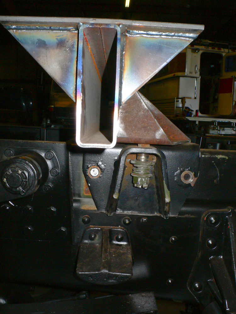
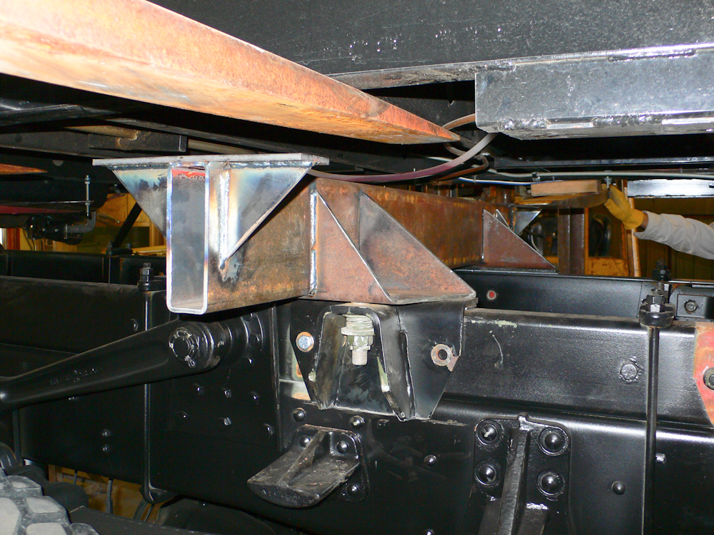
An end view of the
mounting bracket.
The bolt, castle nut and
spring washers were from the stock installation. A new hole will have
to be drilled through the frame member to allow full attachment of the
bracket to the frame in the new location.
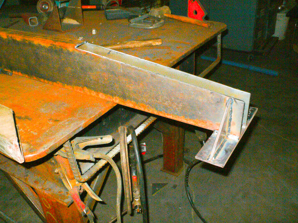
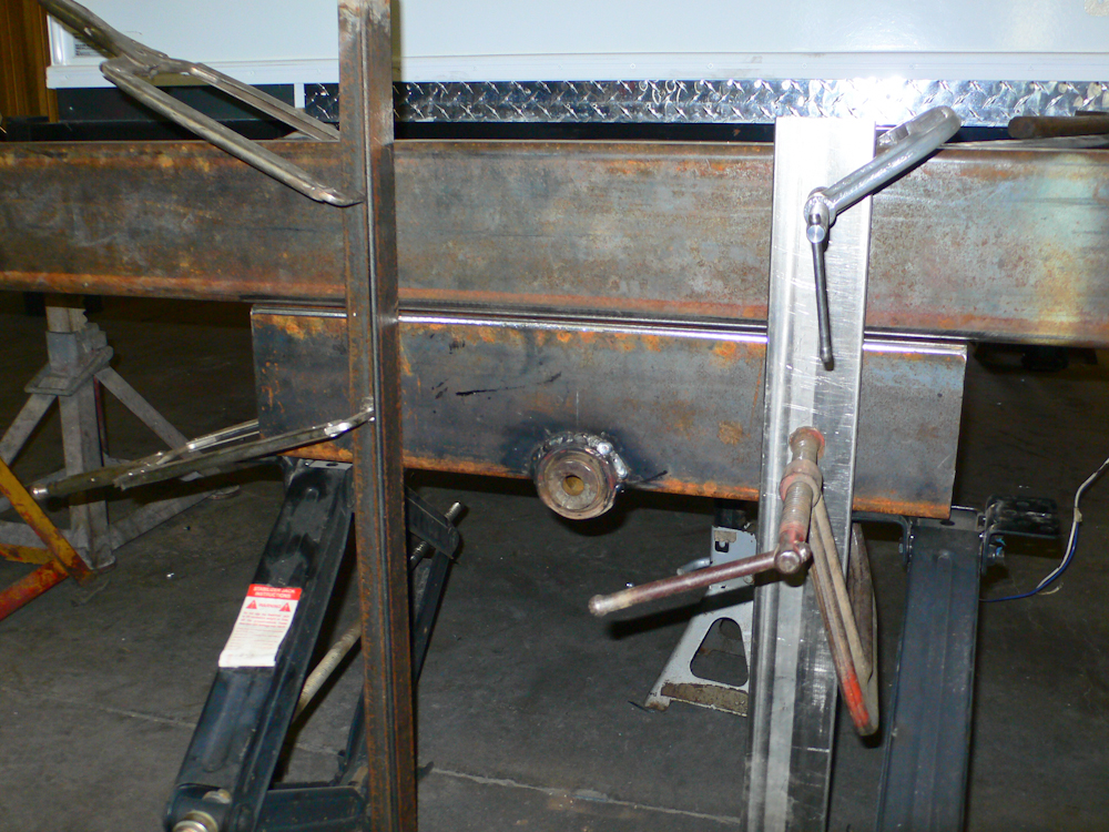
Above is the rear mounting beam. This beam has cut-outs to provide clearance for the plumbing underneath the cabin. Sorry about the high-ISO speckle in the photo, but the flash did not fire.
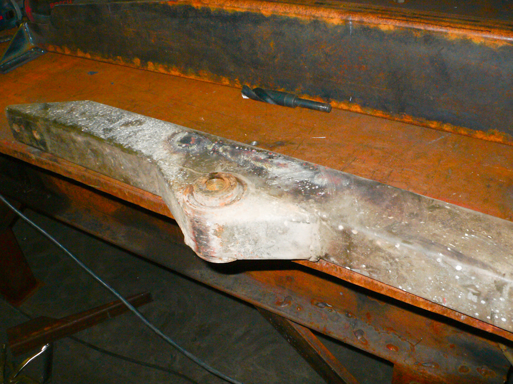
Rob salvaged a mounting
assembly from a radio box that he had sitting around. The
assembly was the donor for the rubber grommet mounting eyes.
The mounting eyes were
cut from the existing frame using a plasma torch and then ground to
provide a clean, smooth surface for welding. An appropriate-sized
recess was then cut into the mounting beam and the eye was welded to
it. The welding was done in slowly in small increments to insure
that the rubber grommet was not melted due to the high heat generated
by the welding process.
The tire frame rack
mounts were welded to the cross member. The final, full "sew-up"
of all the welds will happen later.
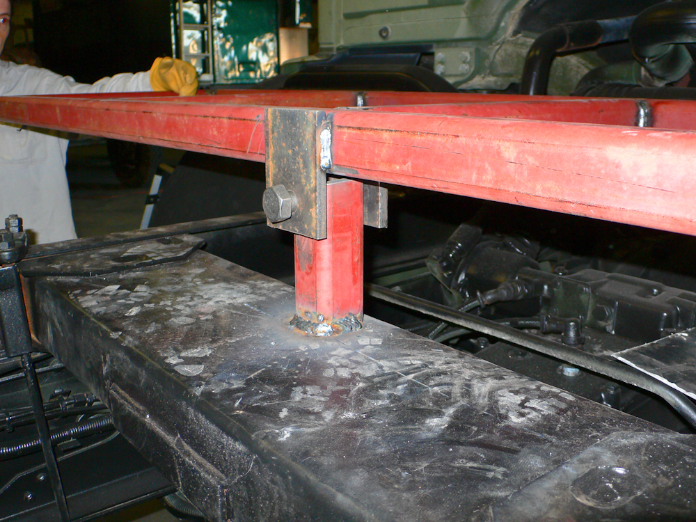
The rear cross member of
the sub-frame was positioned under the camper for a test fit.
There were some straps that supported the gray water tank that had to
be cut and repositioned for the frame member to fit correctly.
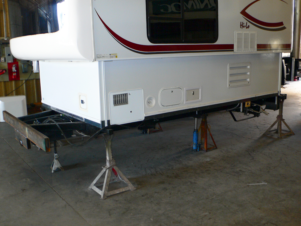
All the junk under the
trailer was removed in anticipation of driving the 1017 under the
trailer. Note the clamps holding the rear frame member in place
at the far right of the photo above.
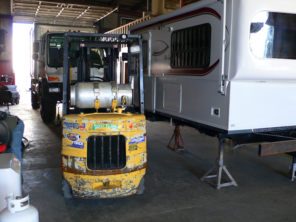
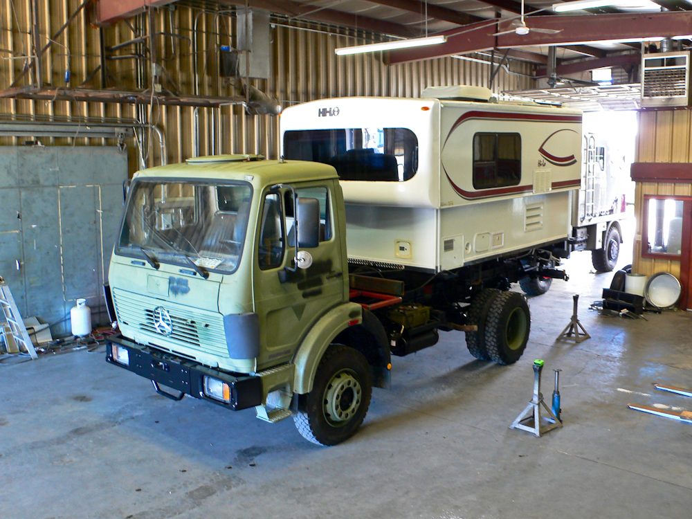
Two fork lifts were
required to lift the trailer. The plan was to get the lifts under
the center of gravity of the trailer, pick it up, and then drive the
1017 under it in the correct location. Then, using the side shift
feature of the fork lifts, the trailer would be set down on the 1017
frame in the correct location for the test fit. Due to the tight
space, positioning the first lift was a bit challenging, but the short
wheelbase won in the end. Note the U500 (for sale) in the
background.
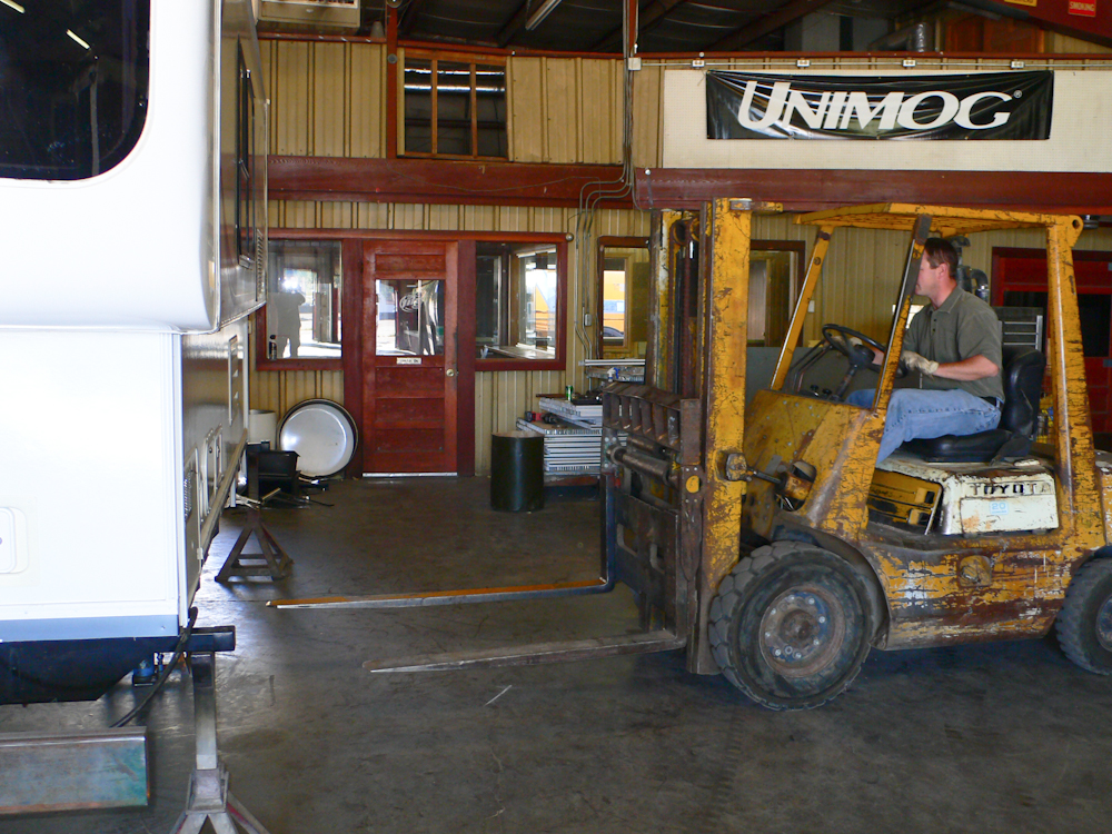
Rob positions the second
fork lift into place.
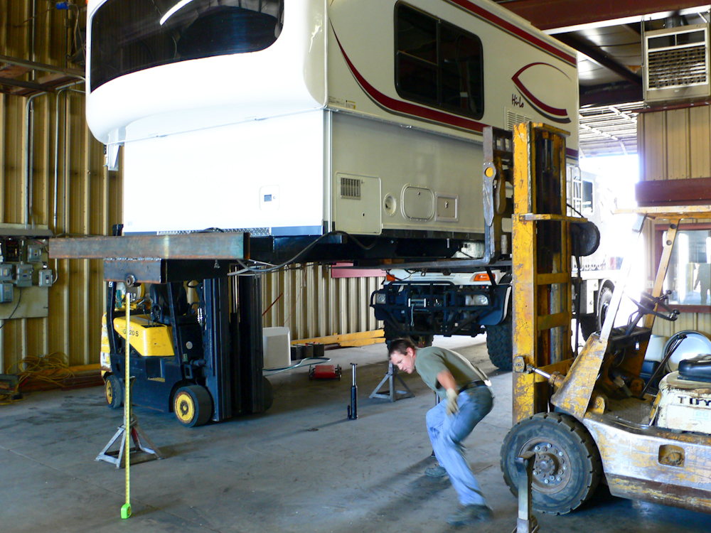
We have lift-off.
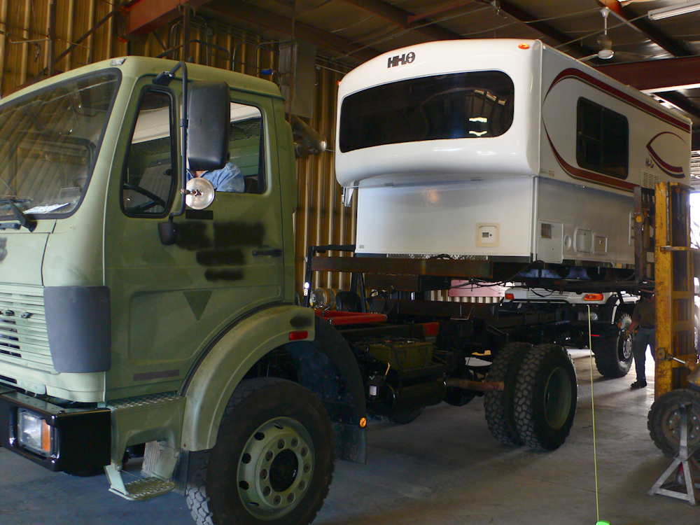
Driving very slowly, with
much spotting, I backed the 1017 under the suspended trailer.
We slowly lowered the
trailer onto the 1017 frame.
We had a small
"situation" with the forks on the passenger side. In the end, we
put some blocks on top of the cross frame and lowered the trailer onto
them. Then, the forks were repositioned, the trailer was raised
and the blocks removed.
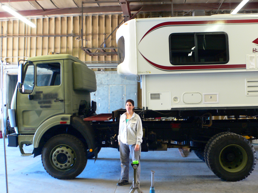
The full weight of the
trailer is on the 1017 frame. Because we disconnected the
electrical setup for the hydraulics, we were unable to lower the top
before picking up the trailer. But, in the end it did not matter;
the weight distribution of the trailer was favorable and it was not an
issue. The trailer sits quite high on the truck; note the height
of the trailer relative to Kathleen (who is about 5'8"). Also
note that the trailer is not sufficiently heavy to cause the frame of
the 1017 to sit level.
A photo taken from the
tailgate of the 1300 shows a different view of the setup.
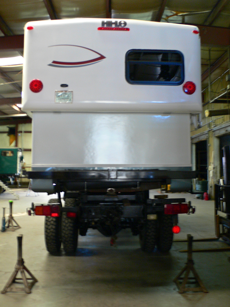
While it is a poor photo
due to insufficient light and a weak flash, the photo above does show
the height of the camper when the top is raised. Our measurements
suggest that the top is about 13.5' when raised. The camper does
not appear to be sitting plumb, but that is an artifact of the angle of
the photograph.
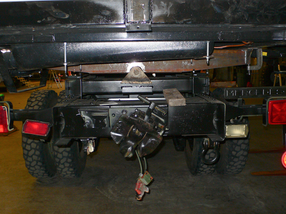
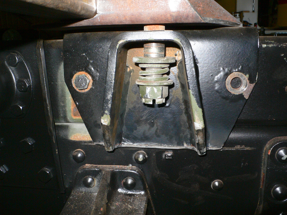
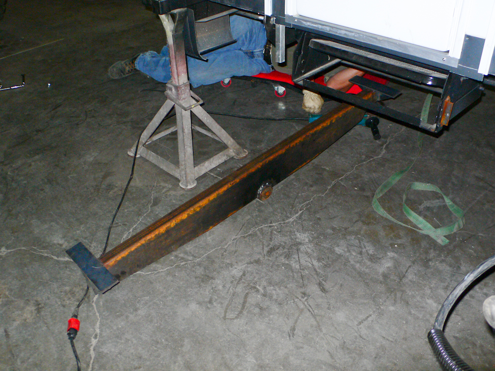
A rear view of the pivot
position with the scrap mount in place for example. The mount
will we re-fabricated with thicker material and then welded to the
cross member.
| Previous Adventure | ||
| Trip Home Page |
Photos
and Text Copyright Bill Caid 2010, all rights reserved.
For your enjoyment only, not for commercial use.