Action Report 20090325
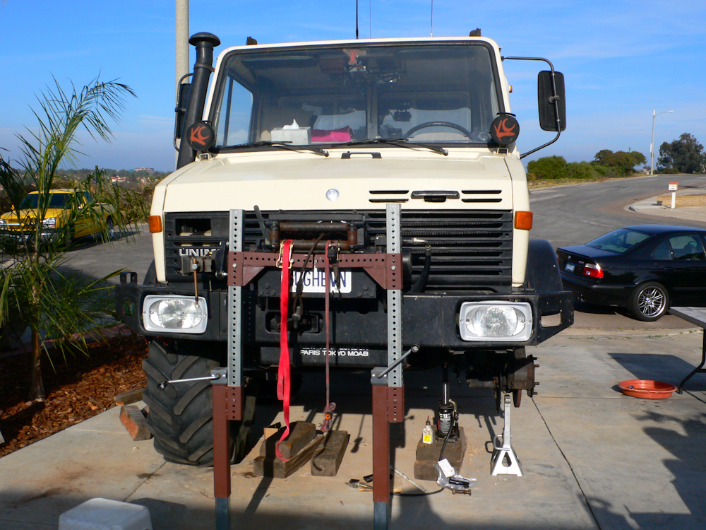
It had been 6 or so years since I have purchased new rubber for my 1300. In that time, the price of tires has more than doubled!! So, after our extended trip to Montana, my inspection of the tires showed that new tires were required, and soon. I priced the Michelin XM-47 tires that we had run with great success, and they were more than $1,000 a tire. While at MogFest, I saw that Kevin Strain had obtained a lift kit for the 1300 and was running military surplus 395/85R20 tires on his rig. This was interesting since these surplus tires were available with 90% tread at a cost of only $150/tire (shipping was extra). I got the tires from the same vendor that Kevin used, Berg General on the east coast. I am told that there are several places to get these tires, you should check in your area to see if you can avoid the big shipping charges. These are heavy duty tires and are rated at 11,000 pounds per tire at 100 psi cold. To put this in perspective, the whole truck only weighs about 14,000 pounds, wet, with camper and gear.
But, these surplus tires were bigger than the XMs (if that is possible) and because of their increased size, they rubbed on the front fenders on full-left-lock turns. The rubbing produced a fearful sound and was at risk of bending the fenders as well as damaging the tire.
Because of Kevin's research, I found out that there is an implement lift for the 1300. The full lift kit consists of some cast iron "pucks" that sit on top of the coil springs and some brackets and bolts used to extend the shocks. I ordered the parts and once the full compliment of parts arrived, we started the installation effort.
Like most things, it was more involved, complex and time consuming than expected. The documentation provided by Mercedes was not very helpful and in the end, it was the help and advice of the Unimog network of owners that saved the day. Special thanks to Pete Lembesis and Sean Philyaw for getting me the information I needed to complete this effort.
In principle, the task seemed easy enough: raise the frame of the truck (not THAT easy when the rig is 14,000 pounds), and undo the coil spring retaining bolts. Then, the puck and puck plates are installed along with longer bolts. Then, the shock extension brackets are installed. Sadly, this was not sufficient to prevent the tires from rubbing on the fender. My email exchanges with Pete told me that I also had to move the front fender and top step to fully complete the job.
The photos below are what we did.
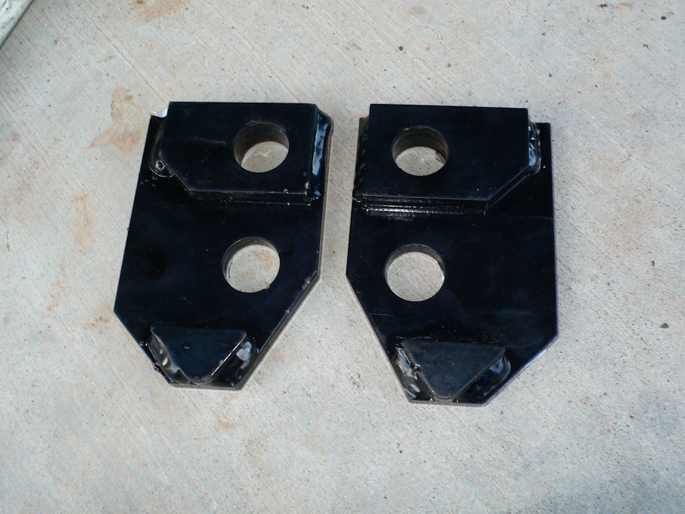
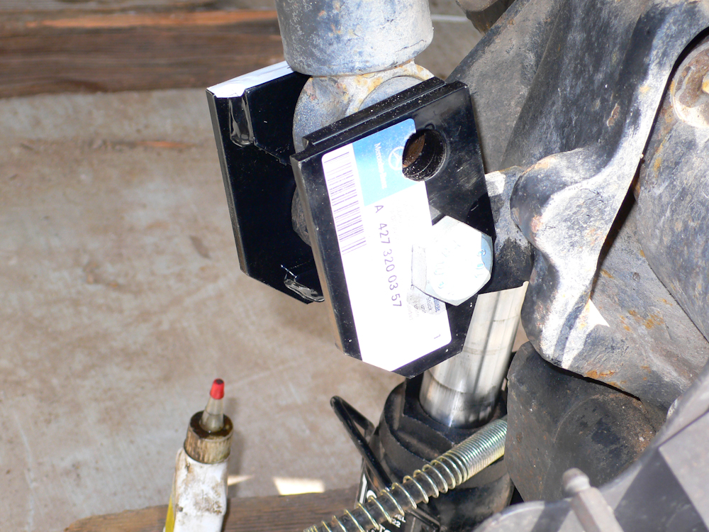
The shock extensions were only intended for the front!! 4 pairs of brackets were sent in the kit, but the brackets do not fit on the rear. This was a mystery, and in the end, I will fabricate a set of extensions for the rear so the truck is symmetrical in articulation. The photo above shows the mirror-image brackets that are used to extend the shocks. The brackets fit around the existing shock mounting brackets on the front axle with the triangle brace facing down. A detailed photo of the installation is shown lower on this page.

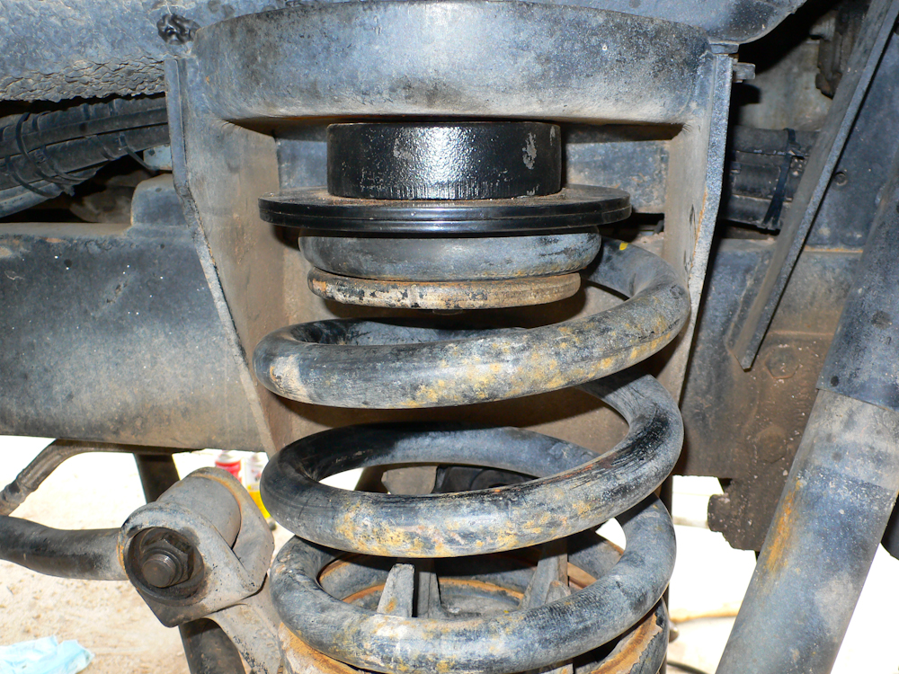
We started on the rear by raising the frame, removing the tires and lowering the axle assembly. Then the attachment bolts that hold the coils in place were removed. In the photo above, you can see the overload springs inside the main coils.
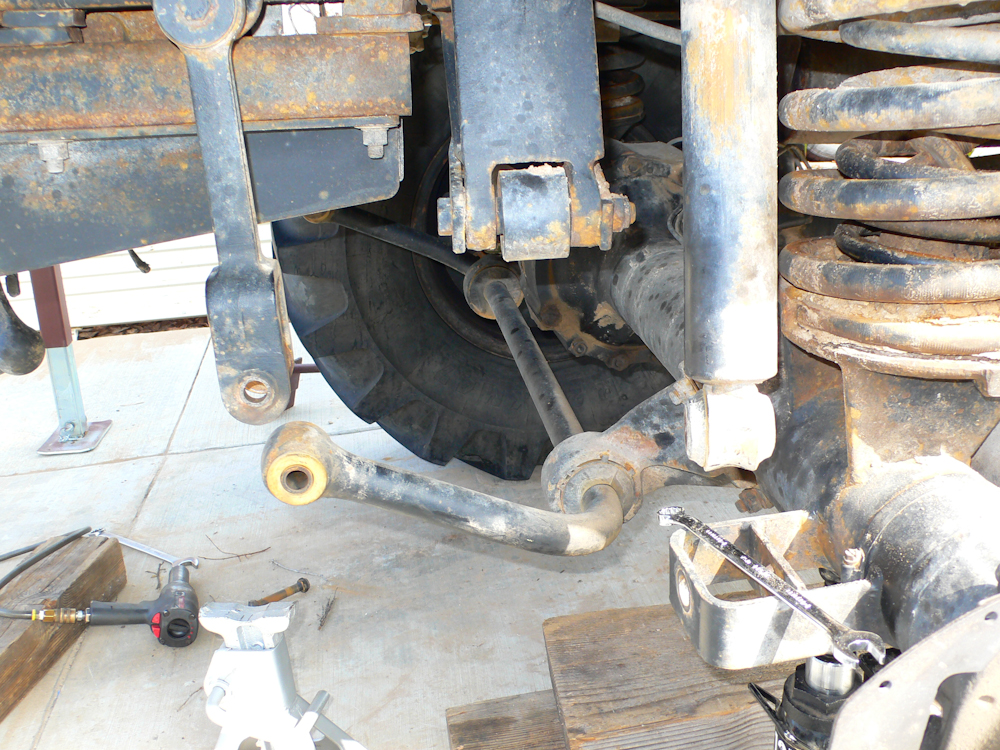
We discovered mid-way into the process that we also had to undo the sway bar to get sufficient droop on the axle to allow the springs to come off.
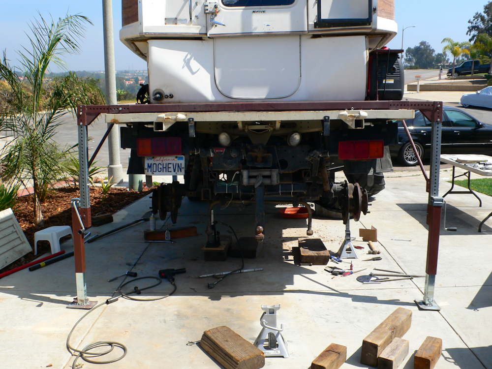
To get the job done, we had to remove both rear tires at once to provide sufficient droop and eliminate the skew in the axle that made reattachment of the springs impossible. In the photo above, you can see the support jacks that were originally designed to support the camper and frame if removal were required. This setup had sufficient strength and lift capabilities to support the entire rear of the truck, including camper.
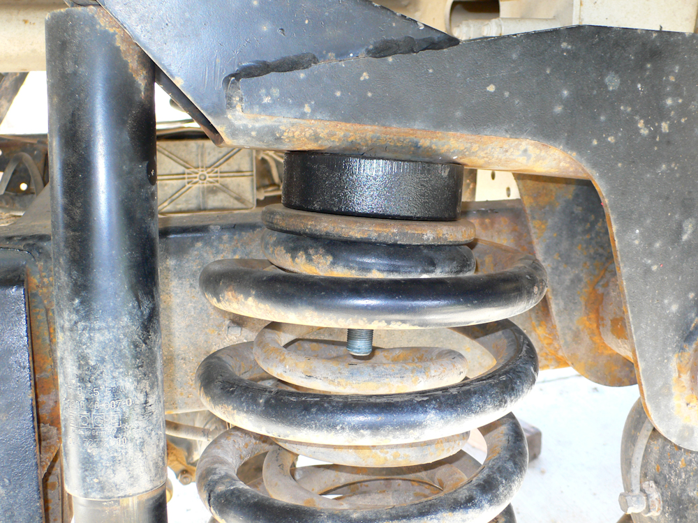
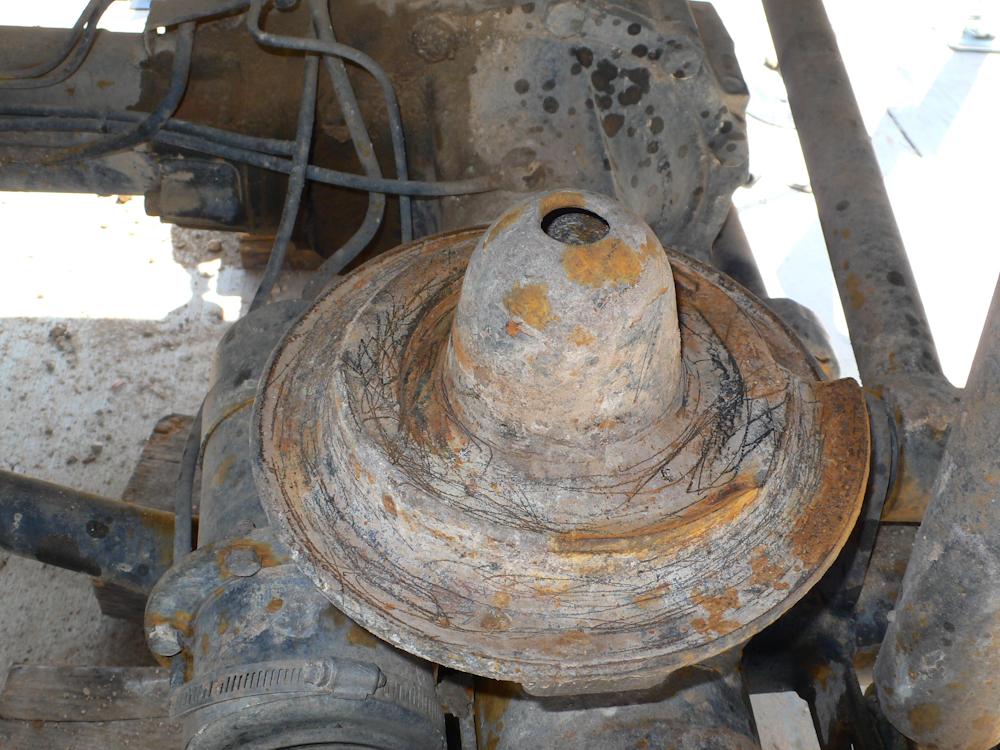
Test installation of the puck. In the final installation, we put the head of the bolt on the bottom and the nut on the top. The first side was pretty easy after the lifting setup was handled.

On the driver's side rear, the spring retainer plate was mis-installed requiring prying and pounding to get it loose.
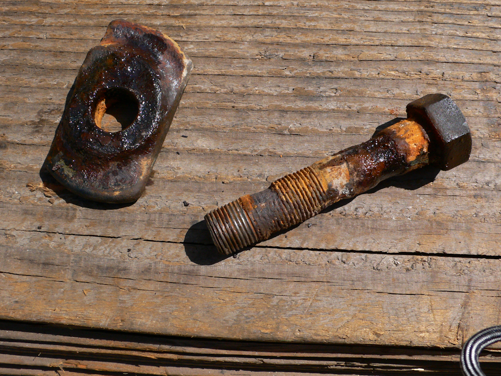
Because it was installed incorrectly, it allowed things to move around and wear the bolts. As you can see, the bolt is well past the end of its useful service life. Due to the corrosion, getting the nut off the bolt was really tough.
Probably due to the incorrect installation, the spring had bottomed out enough times to erode the mount.
The bottom of the assembly was fully caked in nasty salt mud from our last trip to Mexico. After much scraping and wire brushing, it was clean enough to reassemble.
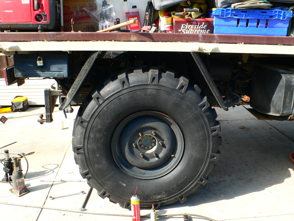
Completed rear axle with tires mounted. The jacks were removed and used for the front.
We repositioned the truck and put the jacks under the front winch. The front is the heavy end of the truck, but the jacks are rated at 5,000 pounds each so we had plenty of safety margin. That said, it was still a bit scary since we had to lift the frame more than 18 inches to allow sufficient axle droop.
The installation of the shock extension brackets was "non-intuitive" to say the least. Thanks to Pete for his photos and advice. Not visible in this photo is the spacer sleeve that fits over the lower bolt between the brackets.
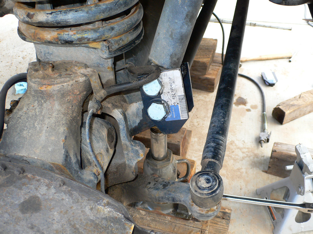
The front bolts were tough to get off, but in the end we did what was required.
The kit had 4 plates, but there was no obvious place to use them in the rear so I put both on the front. Also, I had to drill out the plates as the bolts supplied were much smaller than the hole in the puck and retainer plate. It was easier to expand the hole in the plate than consider the whole assembly sliding around.
Not shown in photos is the brake modulator extension. On the 1300, connected to the rear drive shaft tube is a rod that "senses" the load on the truck. That information is used to modulate the braking pressures delivered to the calipers. Given the lift of the truck, the assembly would "think" that the truck is unloaded and therefore deliver poor braking performance. Upon inspection, it was seen that I could extend the limits of the rod without replacing or modifying the assembly. The original length of the rod was 235mm and I extended it to 250mm to account for the lift in the suspension. This extension resulted in good braking performance, on par with the XM-47 tires and an un-lifted frame.
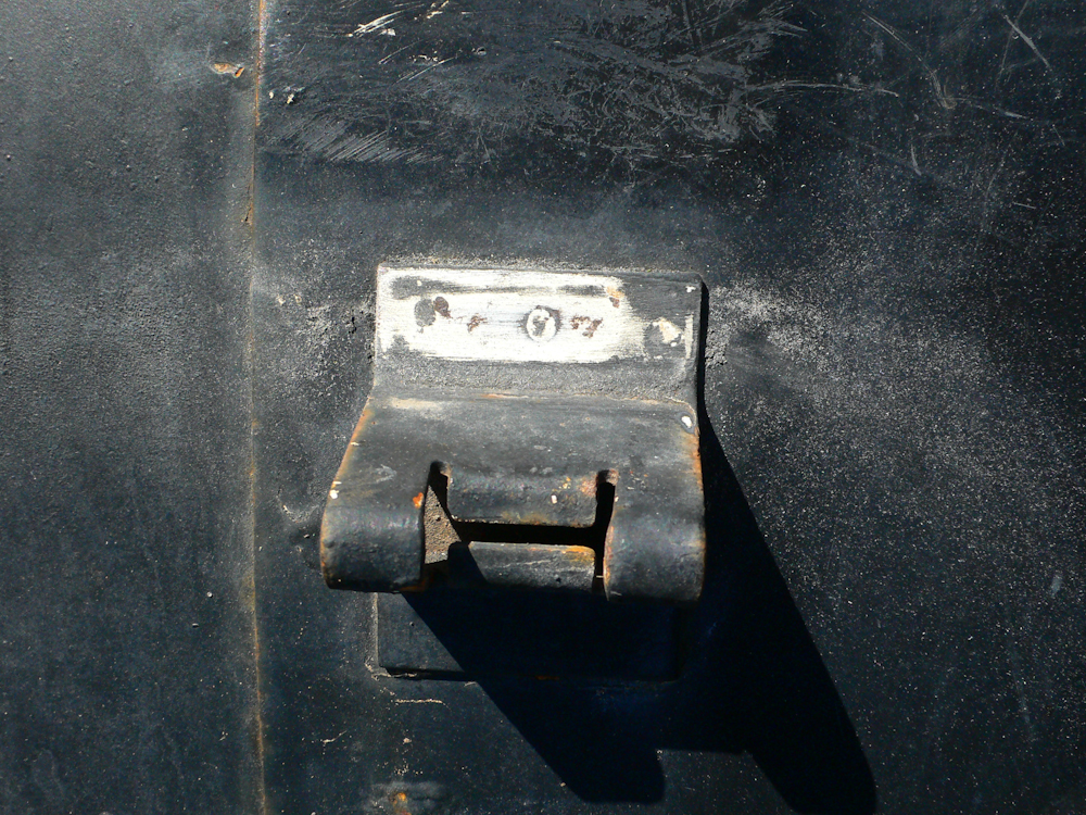
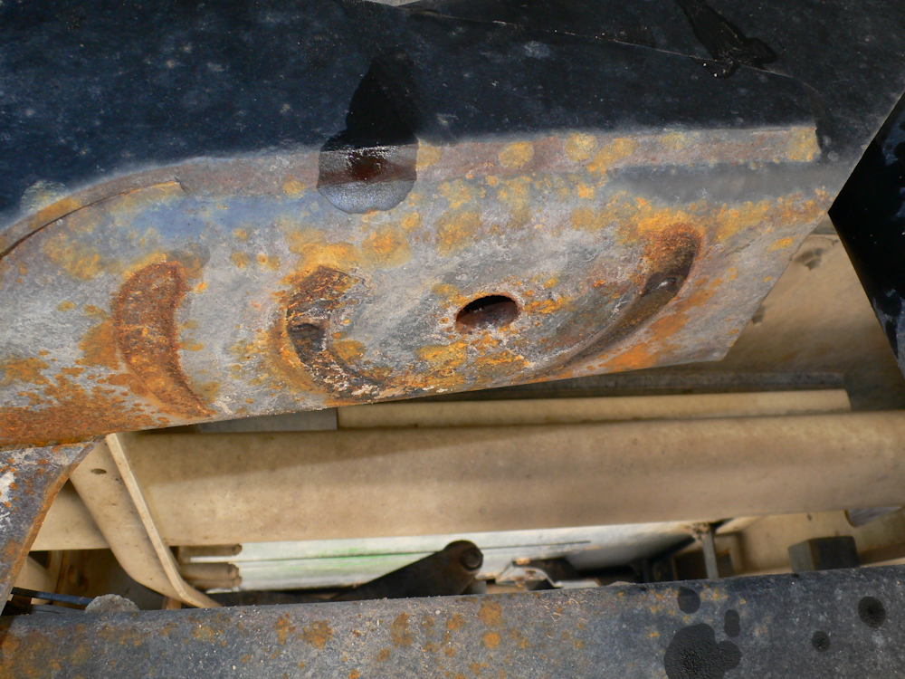
Now for the real hassle. To prevent the tires from rubbing, the fender needed to be pulled aft by about 2 inches. To do this, the bracket that attaches the fender to the top step needed to be moved. Additionally, the step needed to be moved as well. The first action was to remove the bracket which required drilling out the spot welds and then re-welding the bracket in the new, desired location. Above, the position of the spot welds can be seen.
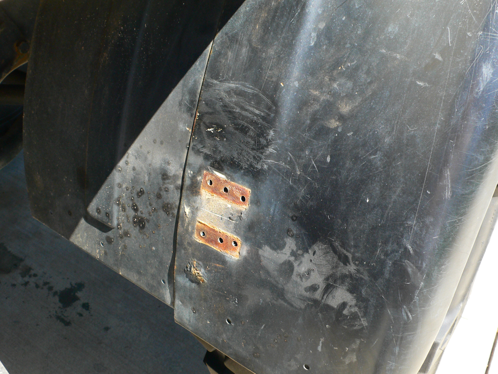
After some drilling and prying, the bracket came off. Note the big bubble of rust under the bracket location. This rust pocket is right beneath where I want to mount the bracket.
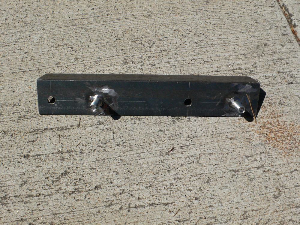
To move the step, a new attachment bracket is needed. Based on Pete's design suggestions, I fabricated one out of a couple of bolts and some 1.5" angle.
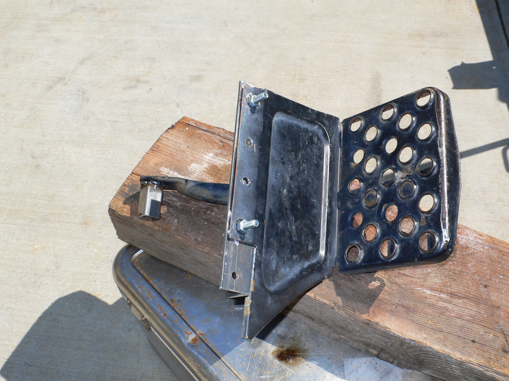
A spacer for the rear mounting support is needed as well. I made mine from 1x1 square tubing. In the photo above, the bracket can be seen attached to the step.
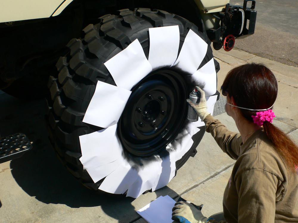
The wheels we were using were "new" so we needed to paint them. Above, Kathleen masks the wheels and spray paints them with medium gloss black.
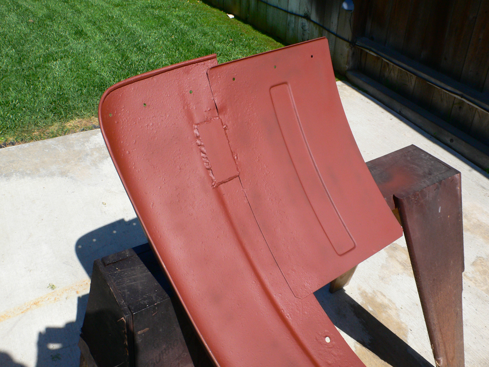
When I attempted to weld on the fender, the rust caused me to burn holes in the material. In the end, I had to put a backup plate on the inside of the fender to cover my damage. The real solution is to get a new fender.
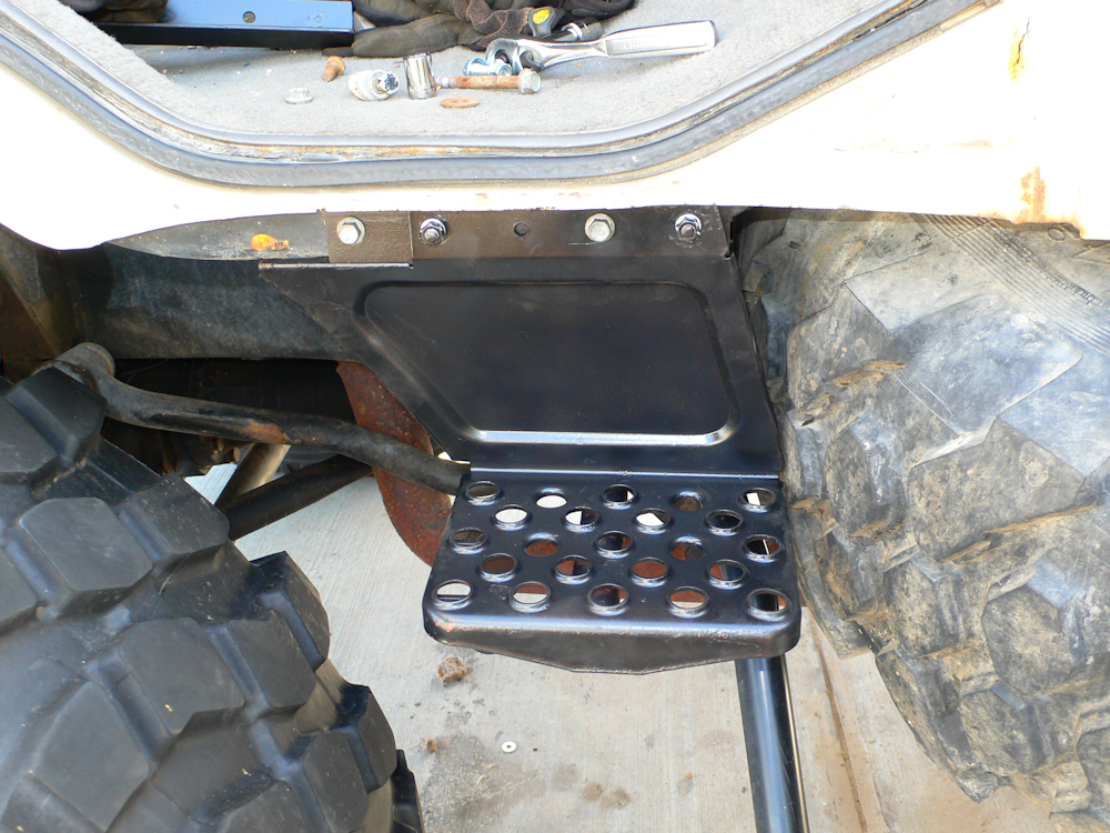
The top step is mounted on the cab. Note that the bracket allowed movement of the step to the rear by about 2". The good news is that it was not that hard to make. The bad news is that there is now an interference with the spare tire that will require removal of the step if I have a flat.
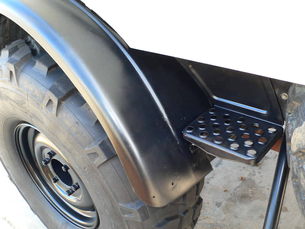
The finished installation.
After the installation was completed, we did a 'wheeling trip to the El Paso mountains. There were some moderately hard trails there, but the trails did have sections that resulted in large amounts of body roll. There were no interferences between the tires and fenders. So, to that end, we have deemed the installations a success.
As for the tires, they work pretty well. They do buzz a bit, but all off-road tires buzz. They seem to have pretty good road manners and did handle off road acceptably well. It should be noted that these tires "want" 10" rims and the Unimog rims are 11". As such, these tires will have a tendency to debead if operated at low air pressures. When we were in the El Paso mountains, I was running at 25 psi. I had no debeads, but was still concerned.
I have been running the tires at 36 psi cold and have had good results. On the way back from El Paso, I ran the pressure up to 60 psi as a test. The truck "hopped" while we drove. We progressively lowered the pressure until the hopping went away and ended up at 38 psi cold. We still got occasional hopping, so on our return from Tucson, we lowered the pressure again to 36 psi and the tires seemed better mannered. Since the installation, we have logged about 1200 miles on these tires and so far, I am pretty happy.
If you have questions about the installation, contact me at bcaid "at" yahoo "dot" com.